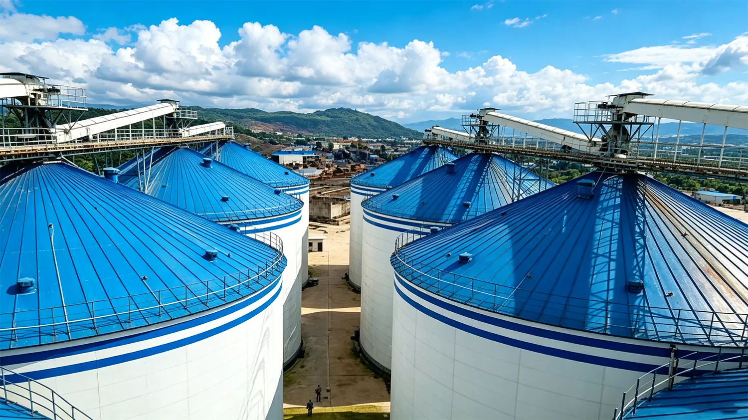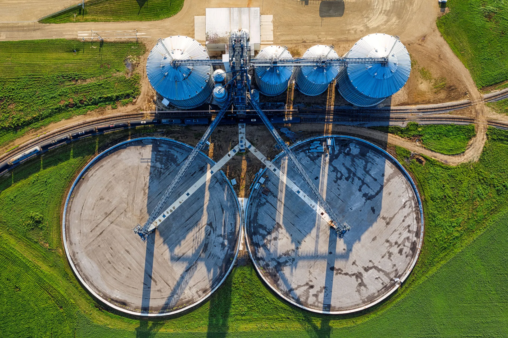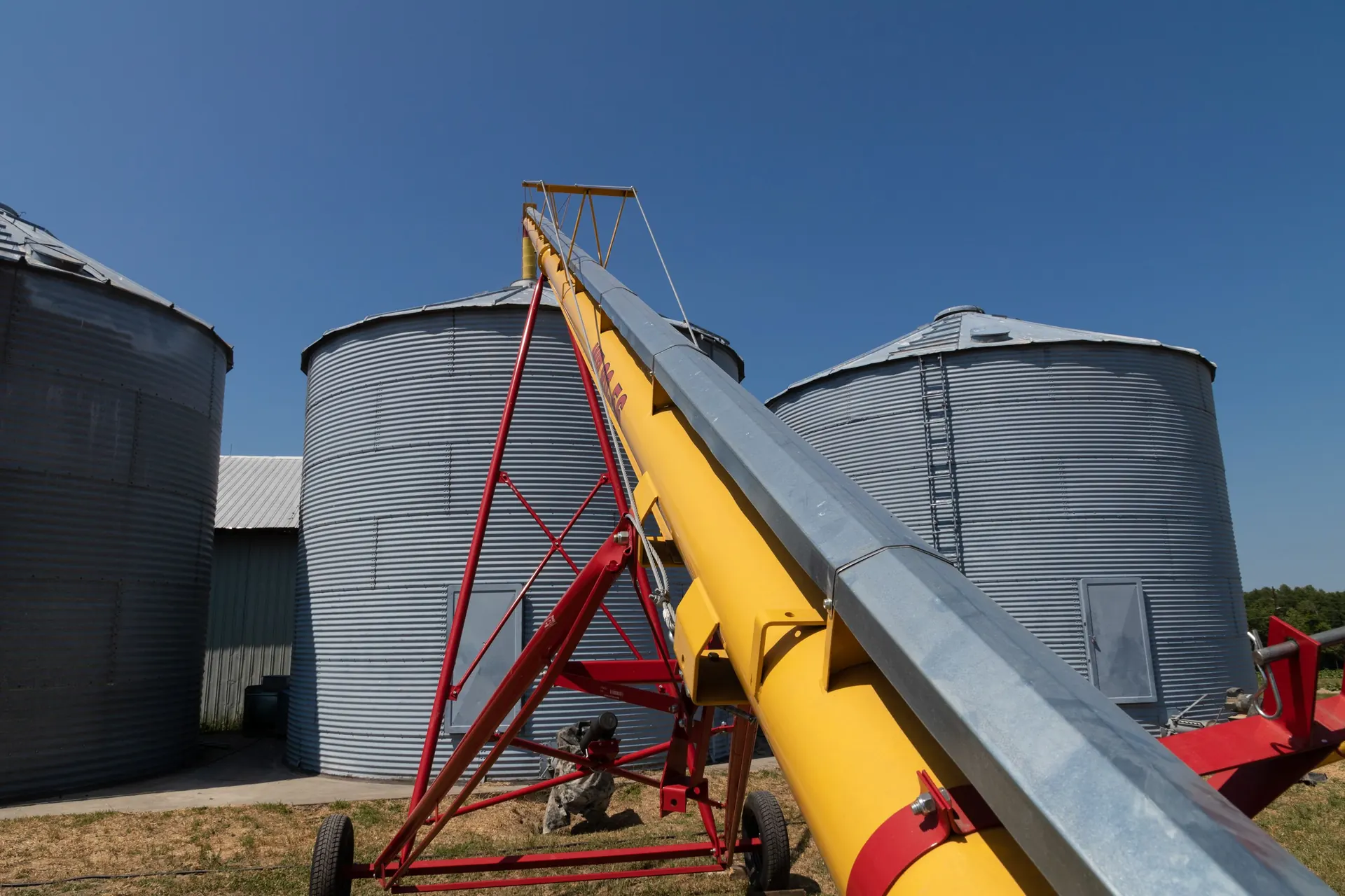
Effective Dust Dust Explosion Prevention in Grain Storage Facilities: En... Prevention in Grain Storage Facilities: En... preservation begins from the ground up. The aeration floor is the single most critical interface between stored grain and the atmospheric control system that protects it. This comprehensive guide examines the engineering principles, material specifications, and installation best practices that define high-performance aeration floor systems for modern grain storage facilities.
Optimizing Grain Storage: The Science of Aeration Floor Design
Aeration floor design represents the convergence of fluid dynamics, structural engineering, and agricultural science. At its core, the system must deliver conditioned air uniformly across the entire Dust Dust Explosion Prevention in Grain Storage Facilities: En... Prevention in Grain Storage Facilities: En... mass at controlled flow rates typically ranging from 0.1 to 0.5 CFM per bushel for cooling aeration. The perforated floor serves as the primary air distribution manifold, transforming high-velocity fan output into gentle, evenly dispersed airflow that traverses interstitial spaces between grain kernels.
The fundamental challenge in aeration floor engineering lies in balancing pressure drop uniformity with structural load Capacity Planning by Crop Type. Dust Dust Explosion Prevention in Grain Storage Facilities: En... Prevention in Grain Storage Facilities: En... exerts substantial lateral and vertical forces on floor components—a 50,000-bushel silo storing corn imposes over 1,800 metric tons of material weight. The aeration floor must withstand these loads without deformation that would compromise airflow pathways or create preferential channels.
Modern aeration floor design perforated floors and air distribution pdf documentation from leading manufacturers specifies performance criteria including pressure uniformity tolerances, maximum allowable channeling percentages, and minimum open area ratios. These engineering standards ensure that every cubic meter of stored grain receives adequate airflow regardless of its position relative to air inlets.

How Perforated Floors Drive Uniform Air Distribution
Perforated floors achieve uniform air distribution through precisely calculated hole patterns, open area percentages, and plenum chamber geometry. The open area—the ratio of perforation area to total floor surface—typically ranges from 3% to 12% depending on grain type, moisture content, and target airflow rate. Finer materials like canola or sunflower seeds require lower open areas to prevent kernel infiltration into the plenum, while coarse grains like corn tolerate higher open areas for maximum airflow efficiency.
The perforation pattern must account for radial pressure gradients within the plenum chamber. Air entering through a central inlet experiences higher static pressure at the center and diminishing pressure toward the silo perimeter. Advanced perforated floor designs compensate for this gradient through variable hole density—higher perforation density near the center transitioning to lower density at the periphery—or through segmented plenum chambers with independent air supply.
Air Distribution Mechanisms in Perforated Systems
Three primary mechanisms govern air distribution through perforated floors:
Diffusion through interstitial spaces: Air exiting perforations disperses into the grain mass through natural void spaces between kernels. Uniform perforation spacing ensures consistent diffusion patterns without dead zones.
Pressure equalization: The plenum chamber beneath the perforated surface acts as a pressure reservoir, dampening fan pulsations and delivering steady, predictable airflow. Plenum depth—typically 150mm to 300mm—is calculated based on silo diameter and required airflow volume.
Boundary layer management: The interface between the perforated floor surface and the grain mass creates a critical boundary layer. Floor surface finish, edge detailing around structural supports, and transition zones at silo walls all influence airflow behavior at this boundary.
Integrating Air Distributors for Maximum Homogenization
The air distributor evenly distributes compressed air to multiple aeration pads or homogenization nozzles in the silo. Proper air distribution is critical for achieving effective homogenization. Precision-manufactured air distributors with uniform flow distribution eliminate the common problem of uneven treatment where center grain receives excessive airflow while perimeter grain remains untreated.
Air distributors function as flow-splitting manifolds that divide a single fan output into multiple equal streams. Each output port connects to a dedicated aeration zone within the floor system. The distributor's internal geometry—including port spacing, throat diameters, and divider vane angles—is engineered to maintain flow balance within ±5% across all outlets regardless of varying downstream resistance.
Critical Design Considerations for Air Distributors
Material selection for air distributors must account for corrosion resistance, structural integrity under pulsating loads, and smooth interior surfaces that minimize turbulence. Galvanized steel, stainless steel, and reinforced polymer composites each offer distinct advantages depending on the stored material's chemical properties and the operating environment's humidity levels.
The integration of air distributors with perforated floor systems requires careful attention to transition ducting. Abrupt diameter changes, sharp bends, and improperly sealed joints create pressure losses that undermine the distributor's precision flow-splitting capability. Engineered transitions maintain laminar flow conditions and preserve the distributor's calibrated output balance.
Hopper Bottom vs. Flat Bottom Silos: Aeration Dynamics Explained
A hopper bottom silo is a type of storage silo designed with a cone-shaped bottom (hopper) instead of a flat floor. This fundamental geometric difference creates distinct aeration challenges and opportunities that engineers must address in floor system design.
Flat Bottom Silo Aeration Dynamics
Flat bottom silos provide the most straightforward aeration floor configuration. The horizontal floor surface allows uniform perforation patterns and consistent plenum depths. However, flat bottom designs require mechanical sweep augers for complete grain discharge, and residual grain left after gravity discharge must be manually or mechanically removed to prevent spoilage that compromises subsequent storage cycles.
The capacity of a flat bottom silo can vary widely depending on factors such as its dimensions, materials of construction, and intended use. Flat bottom silos are commonly used for storing grain, cement, and other bulk materials. Industrial flat bottom silos can have capacities ranging from tens of thousands to hundreds of thousands of cubic meters, with aeration floor areas exceeding 500 square meters in the largest installations.
Hopper Bottom Silo Aeration Dynamics
Hopper bottom silos present unique aeration floor engineering challenges. The conical discharge surface requires specially formed perforated panels that maintain consistent open area while conforming to the slope geometry. Hopper angles—typically 45° to 60° from horizontal—must exceed the grain's angle of repose to ensure complete gravity discharge.
Aeration in hopper bottom silos benefits from natural air concentration toward the center, where grain depth is greatest. However, this concentration can create excessive airflow in the center and insufficient coverage at the upper perimeter. Engineered solutions include multi-zone plenum chambers with independent airflow control and variable perforation density that increases toward the hopper's upper transition ring.

Engineering Specifications for High-Performance Aeration Floors
Engineering specifications for aeration floors must address multiple performance dimensions simultaneously. The following table summarizes critical specification parameters for common grain storage applications:
| Parameter | Corn/Wheat | Soybeans | Canola | Rice |
|---|---|---|---|---|
| Airflow Rate (CFM/bu) | 0.1 - 0.2 | 0.1 - 0.25 | 0.05 - 0.1 | 0.2 - 0.5 |
| Open Area (%) | 5 - 10 | 5 - 8 | 3 - 5 | 8 - 12 |
| Plenum Depth (mm) | 150 - 250 | 150 - 200 | 200 - 300 | 150 - 200 |
| Pressure Drop (in. w.g.) | 2 - 5 | 3 - 6 | 4 - 8 | 2 - 4 |
| Perforation Diameter (mm) | 2.0 - 3.5 | 1.8 - 3.0 | 1.2 - 2.0 | 2.0 - 3.5 |
These specifications represent baseline values that must be adjusted for specific site conditions including altitude, ambient temperature ranges, and target storage duration. Consulting aeration floor design perforated floors and air distribution price documentation from qualified engineers ensures specifications match operational requirements without over-engineering that inflates project costs.
Material Selection and Precision Construction Techniques
Material selection for aeration floors directly impacts system longevity, maintenance requirements, and airflow consistency. The primary material options include hot-dipped galvanized steel, aluminum alloy, reinforced concrete with polymer coating, and engineered composite panels.
Hot-Dipped Galvanized Steel Perforated Floors
Galvanized steel remains the predominant material for aeration floors due to its strength-to-weight ratio, corrosion resistance, and manufacturing precision. The galvanizing process applies a zinc coating of 275g/m² or greater, providing 25-40 year service life in typical grain storage environments. Perforations are punched using CNC-controlled tooling that maintains hole diameter tolerances within ±0.1mm and positional accuracy within ±0.5mm across full panel dimensions.
Panel design incorporates structural ribs and interlocking edges that distribute grain loads to support beams without deflecting the perforated surface. Excessive deflection—even 2-3mm—can create localized airflow restrictions and initiate channeling patterns that degrade aeration uniformity over time.
Composite and Polymer Floor Systems
Advanced composite floor panels offer superior corrosion resistance for aggressive environments including salt-air coastal installations and facilities storing treated grains with chemical residues. High-density polyethylene (HDPE) and glass-fiber reinforced polymer (GRP) panels provide open area consistency that metallic systems cannot match over extended service periods, as they are immune to rust-induced hole enlargement or blockage.
Step-by-Step Installation and Commissioning of Aeration Systems
Process design for grain silos involves Selecting the Right Steel Grade for Grain Bin Construction equipment for loading, unloading, aeration, and monitoring. Critical components include conveyors, elevators, dust collectors, and temperature sensors to ensure efficient and safe grain handling. The installation and commissioning of aeration floor systems demands methodical execution to achieve design performance specifications.
Installation Sequence
Step 1 — Foundation Preparation: The plenum floor slab must achieve surface flatness within ±3mm across any 3-meter span. Deviations beyond this tolerance create uneven air gaps that cause preferential