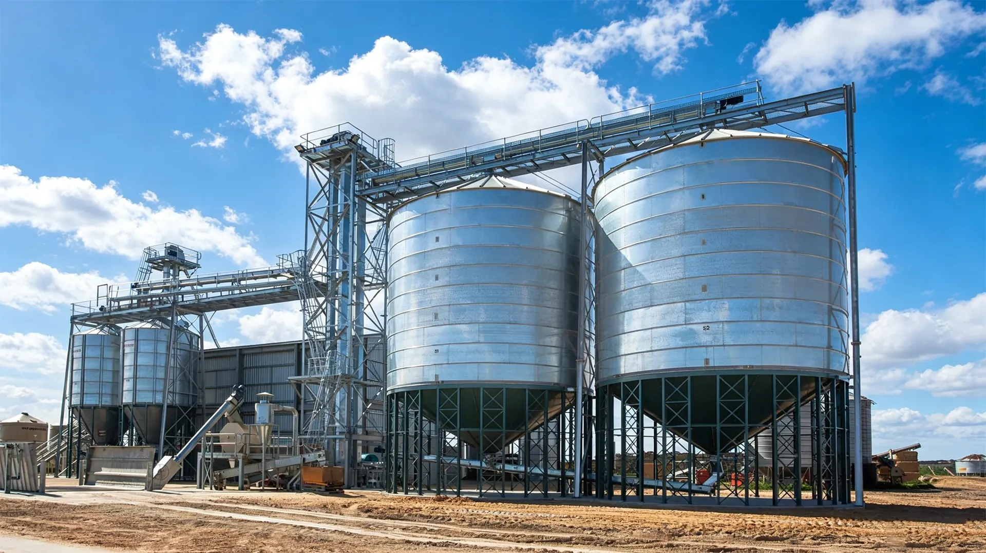
A Dust Explosion Prevention in Grain Storage Facilities: En... silo is not assembled — it is sequenced. The order in which base rings, courses, stiffeners, wind girders and roofs go up determines whether the finished shell stands plumb and round for three decades or develops ovality, seam cracking and discharge problems within a few seasons. This Purchase High-Quality Steel Silo: An Engineer's Guide walks through the complete silo erection sequence, from the site survey to the final load test, with the tolerances and hold points that experienced erection crews treat as non-negotiable.
Key takeaway: In post-erection failure investigations, roughly 8 out of 10 long-term silo defects — out-of-plumb walls, oval shells, leaking seams, uneven discharge — trace back to decisions made in the first 48 hours of erection, not to the Purchase High-Quality Steel Silo: An Engineer's Guide itself. Foundation tolerance, base ring setting and the first course's plumbness set the geometric ceiling for everything above them.
Silo Erection Sequence: Why Build Order Decides Whether Your Silo Lasts 30 Years or 10
Every vertical silo is a stack of tolerances. Each course inherits the deviation of the course below it, and because the shell is a thin-walled cylinder in compression and bending, small geometric errors compound rather than cancel. A 6 mm out-of-round base ring on a 6 m diameter silo looks trivial at ground level. By the time the tenth course is welded on, that same deviation can show up as 25–35 mm of wall lean, a visibly rippled horizontal seam, and a stiffener that no longer sits flush against the shell.
The consequences are practical, not cosmetic. Out-of-plumb walls reduce the effective buckling resistance of the shell under grain load and wind. Oval shells cause uneven grain flow at the discharge, which increases eccentric loading on the foundation. Poorly sequenced welding locks residual stress into the shell, which becomes a fatigue initiation site at every future fill–discharge cycle.
A disciplined erection sequence controls three things simultaneously: geometry (plumb, roundness, elevation), residual stress (weld direction, back-stepping, balanced heat input), and access (rigging paths, laydown order, and the ability to reach every seam before the next course blocks it). Get those three right and the silo behaves as designed. Get them wrong and no amount of later remediation fully recovers the structure.

Pre-Erection Planning Checklist: Site Survey, Access Roads, Permits, and Crew Readiness
Erection begins weeks before steel arrives. The pre-erection phase should produce a signed-off document set covering:
Site survey and geotechnical confirmation
Confirm that the as-built foundation matches the design drawings: anchor bolt coordinates, bolt circle diameter, top-of-concrete elevation, and reinforcement cover. A total station survey of all anchor bolts, logged against theoretical positions, is the single most valuable pre-erection record you will produce. If the foundation was poured by a different contractor than the erector, this survey is the formal handover document that assigns responsibility.
Access roads and crane standing area
Check the route for low-boy trailers carrying the longest panel or the widest rolled course — typically 12–13.5 m long and up to 3.2 m wide. Confirm turning radii, overhead power lines, gate widths, and bridge load limits. At site, the crane pad must carry the outrigger ground bearing pressure, not just the crane's gross weight. On soft ground, timber mats or a compacted crushed-stone pad designed to the crane manufacturer's bearing pressure table is standard practice.
Permits, documentation and crew readiness
Typical requirements include hot work permits, confined space procedures for internal fit-out, working-at-height rescue plans, and lift plans for any single lift exceeding the crane's rated capacity at radius. Crew readiness means verified welder qualifications to the applicable welding procedure specification, calibrated torque wrenches with current certificates, calibrated measuring equipment, and a written inspection and test plan with defined hold points.
Foundation and Anchor Bolt Tolerances: The Error Amplification Nobody Warns You About
This is where most projects either succeed or quietly fail. Anchor bolts set outside tolerance cannot be corrected with shims without distorting the base ring, and a distorted base ring guarantees a non-round first course.
As a working baseline for grain silo foundations, the following tolerances are commonly specified:
| Parameter | Typical Tolerance | Consequence if Exceeded |
|---|---|---|
| Anchor bolt circle diameter | ± 3 mm | Base ring forced into ovality |
| Individual bolt position (radial) | ± 3 mm | Bolt hole elongation required |
| Bolt projection above concrete | + 10 / − 0 mm | Insufficient thread for nut and washer |
| Bolt elevation, bolt to bolt | ± 3 mm | Base ring rocking, uneven grout bed |
| Top of concrete levelness | ± 3 mm over 3 m | Grout bed thickness variation |
| Bolt verticality | 1:100 maximum | Nuts bind, torque cannot be verified |
The amplification effect is straightforward geometry. A bolt circle error of 5 mm at the base translates into a shell radius error that persists all the way to the top course. On a 20 m tall silo, a base ring that is 5 mm out at the circumference can produce a top-of-shell plumb deviation several times larger once welding shrinkage on each course adds its own contribution. Because welding shrinkage is cumulative — roughly 1–2 mm of circumferential pull per vertical seam on a typical panel — the erector must be able to correct in one direction what the foundation handed them in the other.
Practical controls: use a setting template or jig during foundation work, pour a levelling pad or grout strip under the base ring rather than relying on shims alone, and require a certified as-built bolt survey before steel is released from the laydown yard.

Laydown Yard Logistics: Staging, Rigging, and Crane Positioning
Erection speed is decided in the laydown yard. Steel should be offloaded and staged in reverse order of use, with every panel and course match-marked to its drawing position. Match-marking is not a formality: on a 12 m diameter silo, adjacent panels are often rolled to slightly different radii, and swapping two panels creates a visible flat spot that cannot be hammered out.
Key staging rules that experienced crews apply:
- Curved panels stored on edge in cradles, never flat-stacked, to avoid permanent deformation.
- Bolted silo hardware — bolts, nuts, washers, sealant — kitted per course in labelled containers to eliminate sorting at height.
- Crane positioned so the tail swing and boom path clear the foundation, the laydown rows, and any overhead lines. Verify the load chart at the actual working radius, not the maximum radius.
- A defined wind limit in the lift plan, commonly 9–10 m/s for large curved panels, because a 12 m panel acts as a sail with substantial surface area.
- Tag lines on every panel — mandatory, not optional, for controlling rotation during the lift.
Base Ring and Bottom Course: Setting the First Ring True Before Anything Else Goes Up
The base ring is the datum for the entire structure. It is set, levelled and checked before any shell panel is attached.
Setting and checking the base ring
Level the ring on shims or levelling nuts, then verify three things: elevation at eight or more equally spaced points, roundness by measuring diameter at multiple orientations, and concentricity with the foundation centreline. Roundness acceptance is commonly expressed as maximum minus minimum diameter not exceeding 0.5% of nominal diameter — for a 10 m silo, that is 50 mm, but good practice targets half of that.
Bottom course fit-up and welding sequence
Fit the bottom course panels to the base ring, tack in a balanced sequence, and only then complete the vertical seams. Weld vertical seams using a back-step or balanced (alternating opposite sides) technique so shrinkage pulls are distributed rather than accumulating in one direction. The base ring is grouted only after the bottom course is fully welded and re-surveyed — grouting first locks in geometry you may still need to correct.
Jacking vs Crane Erection: Choosing the Right Silo Erection Method for Your Site
| Factor | Jacked Erection | Crane Erection |
|---|---|---|
| Typical diameter range | 3–20 m | 3–30 m and above |
| Practical height | Up to 30 m and beyond | Limited by boom length and load chart |
| Site footprint | Minimal — shell built at ground level | Requires crane pad and laydown area |
| Working at height | Reduced; most welding at ground level | Extensive; platforms and fall protection needed |
| Wind sensitivity | High during jacking of a free shell | High during individual panel lifts |
| Best suited to | Restricted sites, tall silos, welded shells | Large diameters, short build windows, bolted shells |
Jacked erection builds the shell at or near ground level and lifts it progressively with hydraulic jacks and jacking rods, adding courses from beneath. It minimizes high-altitude welding and is often the only practical option where crane access is blocked. Crane erection lifts pre-assembled panels or full course sections into position — faster for large-diameter bolted silos, but it demands a competent lift plan and disciplined wind monitoring.
Course-by-Course Erection Sequence: Welding, Bolting, and Seam Quality Control
The standard sequence per course is: position and