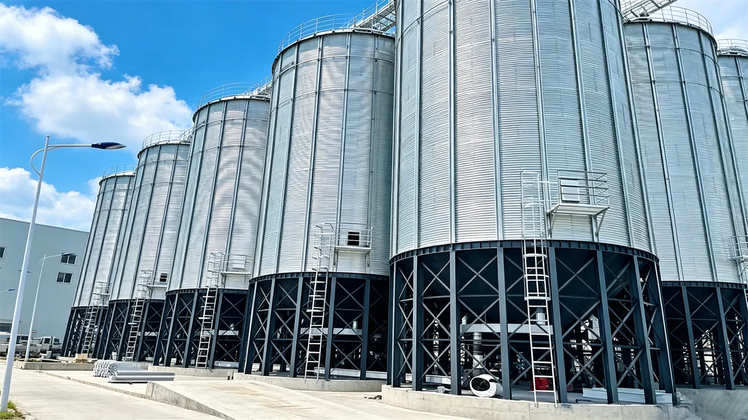
The erection sequence of a spiral steel silo is the single most critical phase in Grain Bin Foundation Settlement: Prevention and Remediati... Bin Foundation Settlement: Prevention and Remediati... Bin Foundation Settlement: Prevention and Remediati...-storage-facilities">Dust Dust Dust Explosion Prevention in Grain Storage Facilities: En... Prevention in Grain Storage Facilities: En... Prevention in Grain Storage Facilities: En... storage construction, determining structural integrity, airtightness, and long-term performance. This comprehensive guide delivers field-proven engineering insights for executing flawless silo erection from foundation to commissioning.
Understanding Spiral Silo Erection Sequence: The Foundation of Rapid Grain Storage Construction
The erection sequence in construction for spiral Dust Dust Explosion Prevention in Grain Storage Facilities: En... Prevention in Grain Storage Facilities: En... silos follows a fundamentally different methodology compared to traditional welded or bolted steel structures. Rather than assembling individual plates or sections, the spiral silo erection process builds the entire shell from a continuous coil of galvanized steel strip, formed and seamed in a single continuous operation on-site.
This approach transforms the construction timeline dramatically. Where a welded silo of comparable size might require 4–6 weeks of on-site labor, the spiral erection sequence compresses this into days. The key lies in the factory-precision coil feeding system that creates a uniform, structurally sound shell without field welding.
Understanding the erection sequence example for spiral silos requires recognizing that every component—from the foundation anchor bolts to the roof hatches—must arrive in precise coordination with the coiling machine's upward progression. Material staging, crew positioning, and accessory installation all follow the spiral's ascending path.
How the Continuous Spiral Seam Process Revolutionizes On-Site Silo Assembly
The spiral seam is the engineering breakthrough that makes rapid erection possible. A steel coil, typically 495mm wide and ranging from 0.8mm to 3.0mm in thickness, is fed into a forming machine that simultaneously bends the strip into a helical shape and interlocks the edges.
This mechanical lock-seam creates a double-folded, airtight joint that runs continuously from the base to the top of the silo. The seam provides both structural strength and hermetic sealing—two properties that traditionally required separate construction steps in welded designs.
The coiling machine advances upward at a controlled rate, typically completing one full revolution every 8–15 minutes depending on silo diameter. This predictable cadence allows project managers to schedule accessory installations, inspections, and material deliveries with precision.
Pre-Erection Planning: Site Preparation, Foundation Requirements, and Material Staging
Successful execution of any steel structure erection procedure begins weeks before the coiling machine arrives. Pre-erection planning encompasses three critical domains: foundation verification, material logistics, and crew readiness.
Foundation Engineering and Verification
The concrete ring wall or slab foundation must achieve minimum 80% design strength before erection begins. Anchor bolts—typically M20 to M30 grade 8.8—must be positioned within ±3mm of design coordinates using certified templates. Any deviation beyond tolerance creates compounding alignment errors as the spiral rises.
Foundation top surface flatness should not exceed ±5mm across the full diameter when checked with a 3-meter straightedge. For large-diameter silos exceeding 20 meters, we recommend laser-level verification of the entire foundation perimeter before accepting the civil handover.
Material Staging and Logistics
Steel coils must be stored on level cribbing, protected from ground moisture, and positioned for direct feed into the coiling machine. A typical 1,500-ton silo requires 15–25 coils depending on wall thickness profile. Each coil weighs 5–8 tons and requires crane access for loading.
Ancillary materials—roof panels, aeration ducts, ladders, and manways—should be staged in sequence of installation. This prevents site congestion and eliminates the need to move completed materials around the site as erection progresses.
Crew Readiness and Safety Protocols
All erection crew members must hold valid working-at-heights certification and demonstrate competency in the specific coiling machine model being deployed. A pre-erection safety briefing should cover emergency procedures, communication protocols, and daily hazard assessments. Personal fall arrest systems are mandatory once the shell exceeds 2 meters in height.
Equipment Mobilization and Calibration
The coiling machine, hydraulic power unit, and forming rolls require calibration before erection begins. Verify that roll gaps are set to the specified strip thickness, hydraulic pressures meet manufacturer specifications, and all safety interlocks function correctly. Maintain a calibration log as part of the quality documentation package.
Step-by-Step Spiral Silo Erection Sequence: From First Coil to Final Course
The actual erection sequence follows a disciplined progression that experienced crews execute with repeatable precision. Below is the standard sequence used on projects worldwide.
Step 1: Base Plate and First Course Anchoring
The spiral forming machine is positioned on the foundation, and the first coil is fed through the forming rolls. The initial course is carefully aligned to the anchor bolt pattern and secured with specified torque values. This first revolution establishes the reference plane for the entire silo.
Step 2: Continuous Spiral Formation
Once the base is secured, the coiling machine operates continuously, forming the spiral seam as the steel strip feeds through. The machine climbs on the completed shell, using the previously formed wall as its track. Each new coil is butt-welded to the trailing end of the previous coil using a certified MIG welding procedure.
Step 3: Wall Shell Completion
The spiral continues until the design height is achieved. At this point, the top edge is trimmed to a level plane, and the top angle ring is installed to provide structural rigidity and a mounting surface for the roof structure.
Step 4: Roof Structure and Accessory Installation
With the shell complete, the roof structure—typically a conical steel with galvanized decking—is assembled. Manways, temperature monitoring cables, and level indicators are installed according to the project specification.
Lock-Seam Technology: Achieving Structural Integrity and Airtightness Without Welds
The lock-seam joint is the defining feature of spiral silo construction and the primary reason this erection sequence delivers superior performance. The seam is formed by a five-fold interlock: the edge of each new wrap folds over the edge of the previous wrap, creating a mechanical bond that resists both radial hoop stress and vertical shear.
Unlike welded seams, the lock-seam does not require heat application, eliminating the risk of zinc burn-off on galvanized material and the potential for heat-affected zone corrosion. The seam's inherent flexibility also allows the shell to absorb minor foundation settlement without cracking.
For applications requiring enhanced airtightness—such as nitrogen-purged storage for insect control—the lock-seam can be supplemented with food-grade sealant applied during the forming process. This creates a hermetic seal capable of maintaining oxygen levels below 5% for extended storage periods.
Erection Speed and Labor Efficiency: Why Spiral Construction Outperforms Welded Alternatives
The economic advantage of the spiral erection sequence becomes clear when comparing labor hours per ton of storage capacity. The following table illustrates typical project metrics:
| Silo Type | 1,000-Ton Capacity Erection Time | Crew Size | Labor Hours |
|---|---|---|---|
| Spiral (Lock-Seam) | 7–10 days | 6–8 workers | 480–800 |
| Bolted Steel | 25–35 days | 8–12 workers | 2,400–4,200 |
| Welded Steel | 35–50 days | 10–15 workers | 3,500–7,500 |
These figures demonstrate why the fabrication and erection of steel structures via spiral methodology has become the preferred approach for commercial grain storage worldwide. Reduced on-site time also translates to lower weather risk, reduced site overhead costs, and earlier revenue generation from the storage asset.
Material Specifications and Coil Selection for Optimal Erection Performance
Material selection directly impacts erection speed and final silo performance. The following specifications represent industry best practice for grain storage applications:
- Base material: Hot-dip galvanized steel strip to ASTM A653 or equivalent, Z275 (275 g/m² zinc coating) minimum
- Thickness range: 0.8mm to 3.0mm, with variable-thickness designs using thicker gauges at lower courses where hoop stress is maximum
- Yield strength: Minimum 250 MPa (36 ksi) for standard applications; 350 MPa for high-strength designs
- Coil dimensions: 495mm wide × 5–8 tons per coil, with inner diameter of 508mm or 610mm to match the coiling machine mandrel
For corrosive environments such as coastal locations or storage of high-moisture materials, stainless steel coils (304 or 316L grade) can be processed through the same erection sequence with adjusted forming parameters.
Quality Control During Erection: Inspection Points and Tolerance Management
Quality control is embedded throughout the erection sequence, not deferred to a final inspection. The following checkpoints are mandatory at each phase:
Dimensional Tolerances
- Shell diameter: ±10mm from design
- Vertical plumbness: Maximum 1:500 of silo height
- Seam interlock: Full engagement verified by visual inspection and periodic pull testing
- Anchor bolt torque: Verified at 100% of bolts using calibrated torque wrenches
Documentation Requirements
A comprehensive steel structure erection procedure PDF should document every inspection point, responsible party, and acceptance criteria. This documentation forms part of the project quality record and is essential for warranty activation. Many clients request the erection sequence PDF as part of the handover documentation package for their asset management records.
Integrating Aeration, Ventilation, and Accessories During the Erection Sequence
Unlike welded silos where accessories are installed after shell completion, the spiral erection sequence allows for simultaneous installation of internal components as the shell rises. This integration approach reduces total project duration and eliminates the need for confined-space entry during a separate construction phase.
Aeration ductwork is typically installed on the foundation before erection begins, with the spiral shell forming around it. Temperature monitoring cables are attached to the inner wall surface at designated elevations as the coiling machine passes. Roof-mounted ventilation fans and natural ventilation ducts are installed during the roof construction phase.
This parallel installation approach requires precise coordination between the erection crew and accessory installers, but the time savings are substantial—typically 5–8 days on a large-capacity silo project.
Weather and Environmental Considerations That Impact Erection Timelines
The erection sequence is sensitive to several environmental factors that must be managed proactively:
- Wind speed: Coiling operations should cease when sustained winds exceed 40 km/h (25 mph) to prevent shell deformation and ensure crew safety
- Temperature: Steel coil properties change in extreme cold; below -15°C, pre-heating of coil ends may be required for proper seam formation
- Precipitation: Rain or snow on the forming machine tracks can cause slippage; covers and drainage provisions are essential
- Lightning: As the silo rises, it becomes a potential lightning target; temporary grounding must be maintained throughout erection
Project schedules should include 15–20% weather contingency for outdoor erection sequences in temperate climates, and up to 30% in regions with extended wet or cold seasons.
Common Erection Sequence Mistakes and How to Avoid Costly Rework
After two decades of field experience, we have identified the most frequent errors that compromise silo performance and delay project completion:
- Inadequate foundation preparation: Rushing erection onto an out-of-tolerance foundation creates alignment issues that compound with every revolution. Always complete a formal foundation acceptance survey before mobilizing the coiling machine.
- Improper coil storage: Coils stored directly on ground or without end caps absorb moisture, leading to seam corrosion and premature failure. Use elevated cribbing and protective covers.
- Incorrect anchor bolt torque: Under-torqued bolts allow shell movement; over-torqued bolts strip threads or crack concrete. Use calibrated tools and verify at 100% of locations.
- Skipping intermediate inspections: Waiting until shell completion to check tolerances means errors discovered late require extensive rework. Inspect every 5 meters of rise.
- Poor coil splice welding: Butt welds between coils must be full-penetration and ground flush to pass through the forming machine without jamming or damaging rolls.
Commissioning and Post-Erection Testing: Validating Silo Performance Before Fill
Completion of the erection sequence triggers a structured commissioning protocol that validates silo performance before grain introduction:
- Visual inspection: 100% of shell interior and exterior surfaces examined for damage, corrosion, or seam defects
- Airtightness testing: Pressure decay test to verify shell integrity; standard acceptance criterion is