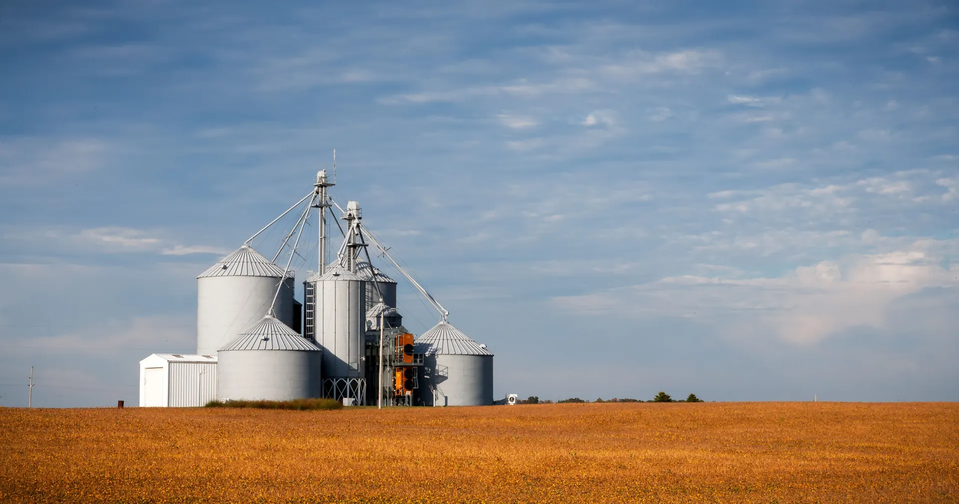
Selecting the correct Dust Dust Explosion Prevention in Grain Storage Facilities: En... Prevention in Grain Storage Facilities: En... bin configuration directly impacts operational efficiency, storage capacity, and long-term return on investment. This comprehensive guide examines the critical differences between flat-bottom and hopper-bottom bin designs, providing the technical insights engineers and operators need to make informed decisions.

1. Introduction to Flat-Bottom vs. Hopper-Bottom Bin
The Dust Dust Explosion Prevention in Grain Storage Facilities: En... Prevention in Grain Storage Facilities: En... storage industry relies on two primary structural configurations: the flat-bottom bin and the hopper-bottom bin. Each design addresses fundamentally different operational requirements, and understanding their engineering distinctions is essential for specifying the correct solution.
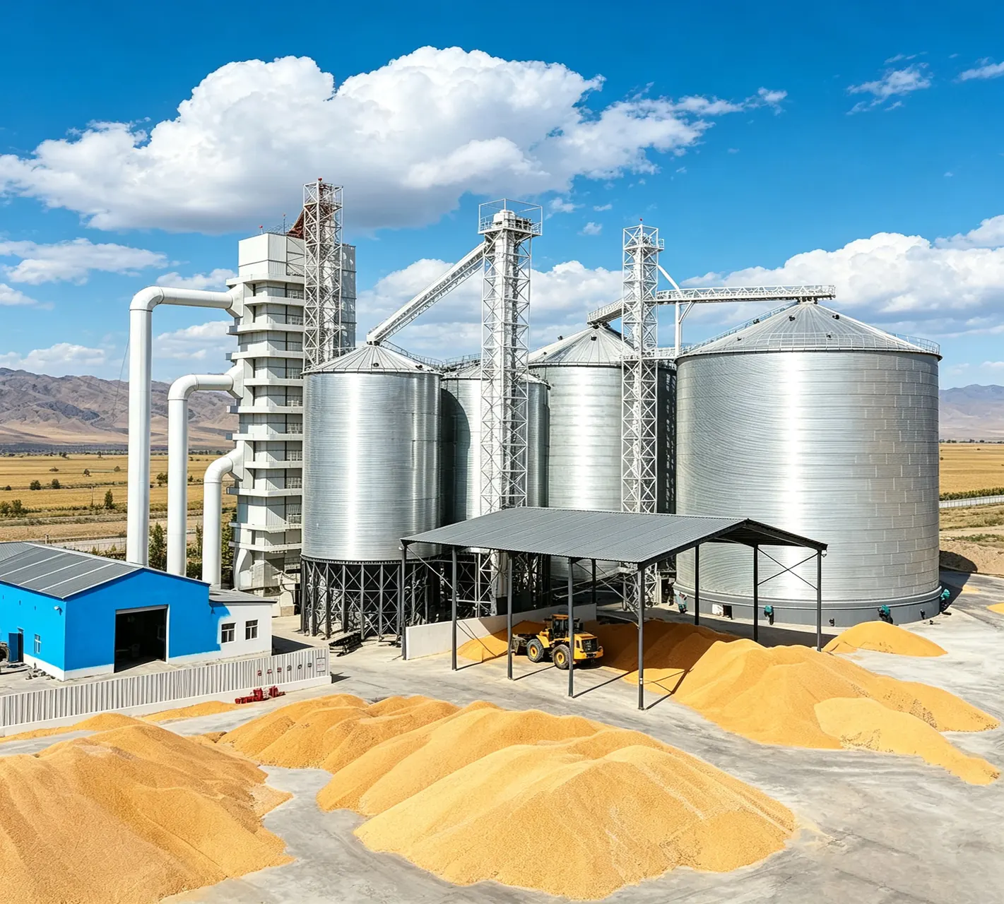
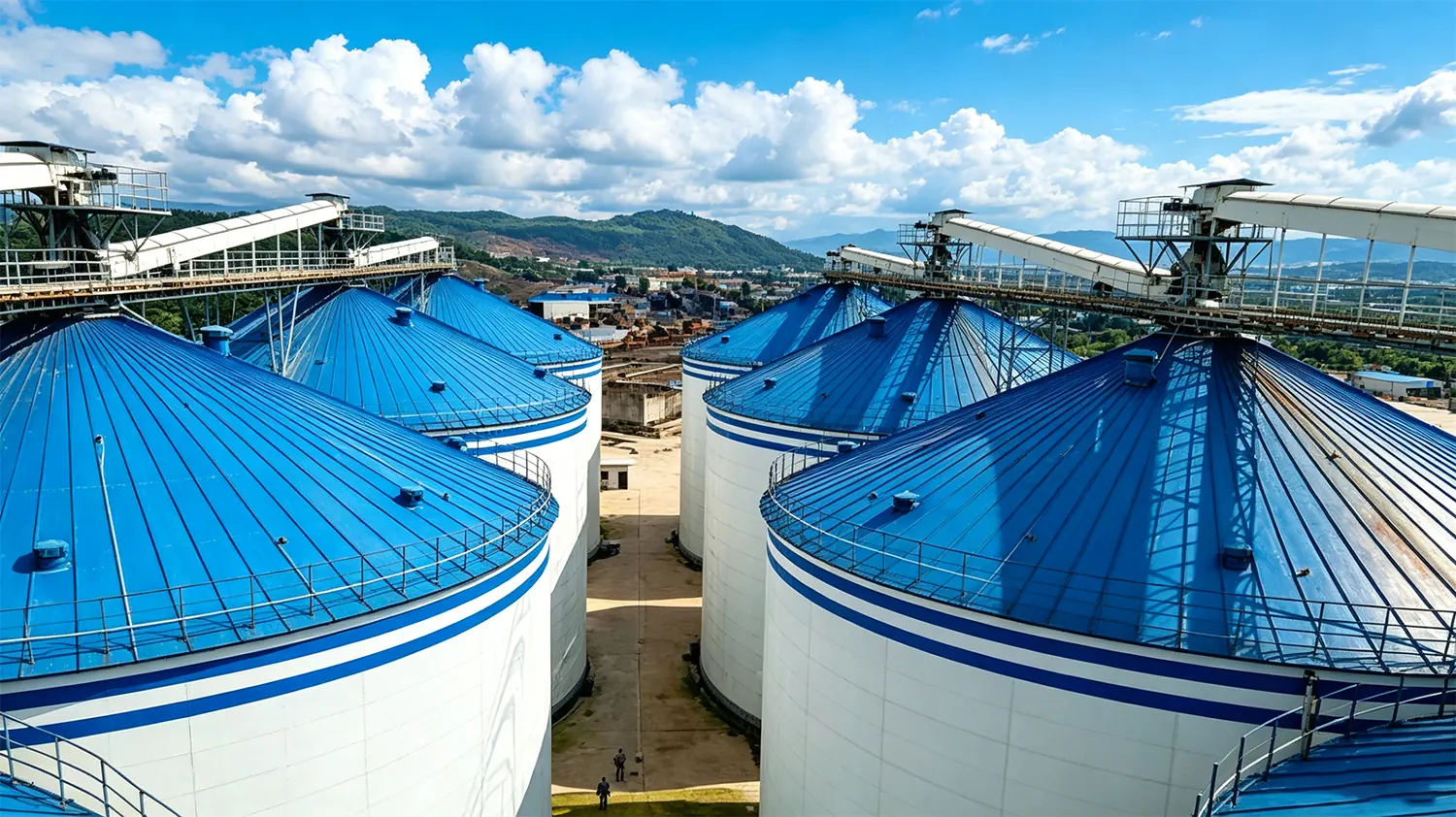
Flat-bottom bins feature a level concrete or steel base with Dust Dust Explosion Prevention in Grain Storage Facilities: En... Prevention in Grain Storage Facilities: En... distributed across the entire floor area. They are engineered for maximum volumetric efficiency, storing thousands to hundreds of thousands of bushels within a single structure. The flat floor design allows for uniform grain distribution through automated filling systems and accommodates center draw-off mechanisms.
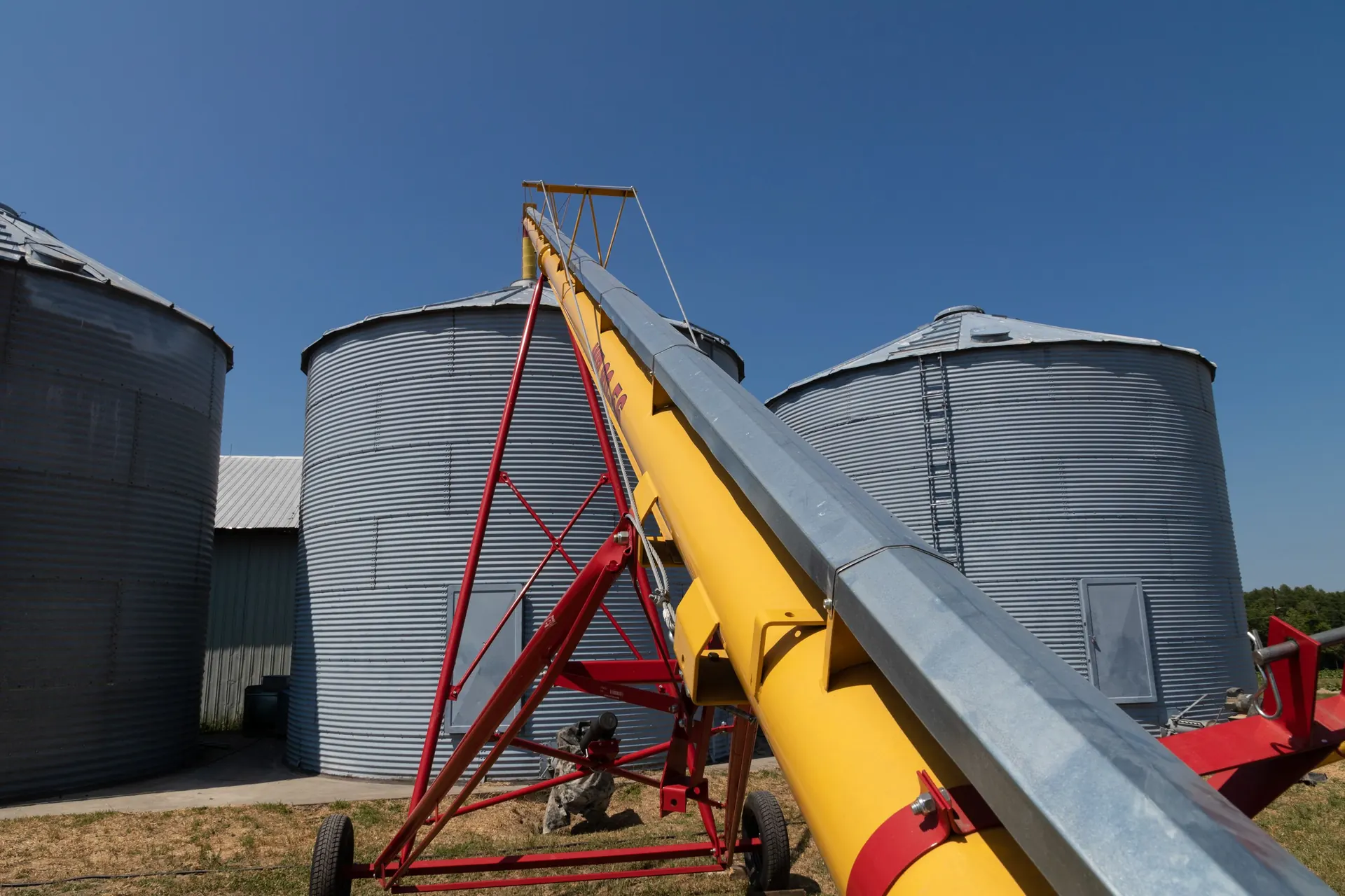
Hopper-bottom bins, by contrast, terminate in a conical or pyramidal discharge hopper at the base. This configuration leverages gravity for complete or near-complete self-discharge, eliminating the need for extensive sweep auger systems in many applications. The hopper angle must exceed the angle of repose of the stored material to ensure mass flow discharge.
The choice between these configurations influences every aspect of the storage system: foundation design, material handling equipment, aeration systems, structural loading, and total project economics.
2. Key Technical Specifications of Flat-Bottom vs. Hopper-Bottom Bin
Capacity Ranges and Dimensional Parameters
Flat-bottom grain bins span the widest capacity spectrum in the industry. Small farm-scale units begin at approximately 1,000 bushels (roughly 35 cubic meters), while industrial installations exceed 1,000,000 bushels (approximately 35,000 cubic meters). Common diameters range from 15 feet (4.6 meters) to over 150 feet (45.7 meters) for welded steel construction.
Hopper-bottom bins typically serve the smaller-to-medium capacity range, from approximately 500 bushels to 50,000 bushels. The hopper structure imposes practical limits on overall diameter and height-to-diameter ratios. Standard diameters span from 9 feet (2.7 meters) to 36 feet (11 meters) for most agricultural applications.
Flat-Bottom Bin Specifications
- Capacity: 1,000 – 1,000,000+ bushels
- Diameter: 15 ft – 150+ ft (4.6 – 45.7+ m)
- Eave height: Up to 60+ ft (18+ m)
Hopper-Bottom Bin Specifications
- Capacity: 500 – 50,000 bushels
- Diameter: 9 ft – 36 ft (2.7 – 11 m)
- Total height: Up to 45 ft (13.7 m)
Discharge System Requirements
The discharge mechanism represents the most significant operational difference between these configurations. Flat-bottom bins require a sweep auger system to move grain from the outer perimeter to the center draw-off point after gravity flow is exhausted. This sweep auger typically travels along a track mounted on the floor, collecting residual grain and conveying it to the center sump.
Hopper-bottom bins utilize gravity discharge through the hopper opening. A well-designed hopper achieves 95-99% self-discharge, with only minimal residual material requiring manual or mechanical assistance. The discharge opening typically ranges from 8 inches to 24 inches in diameter, depending on bin capacity and material flow characteristics.
3. Design Considerations for Flat-Bottom vs. Hopper-Bottom Bin
Foundation and Structural Loading
Flat-bottom bins impose uniformly distributed loads across the entire base area, requiring engineered concrete slab foundations designed for the total weight of stored grain plus structural dead load. The foundation must account for soil bearing capacity, groundwater conditions, and seismic loading. For large-capacity installations, pile-supported foundations may be necessary when soil conditions cannot support the concentrated loads.
Hopper-bottom bins concentrate their loads through support legs or a ring beam to discrete foundation points. This design reduces the total concrete volume required but demands precise engineering of the support structure. Each leg footing must resist both vertical compression and lateral forces from wind loading on the elevated bin body.
Material Flow Characteristics
Grain flow behavior differs substantially between these configurations. Flat-bottom bins operate on a funnel flow (first-in, last-out) principle during discharge, where grain from the center withdraws first while material at the walls remains static until the sweep auger engages. This flow pattern can lead to uneven aeration and potential spoilage in the outer zones if not properly managed.
Properly designed hopper-bottom bins achieve mass flow (first-in, first-out), where all material in the bin is in motion during discharge. This flow pattern provides more uniform residence time, reduces segregation, and minimizes the risk of hot spots developing in stagnant grain zones.
Aeration System Integration
Aeration floor design varies significantly between the two configurations. Flat-bottom bins accommodate full-floor aeration systems with perforated or slotted floor panels embedded in the concrete foundation. These systems deliver uniform air distribution across the entire grain mass, with typical airflow rates of 1/10 to 1/5 CFM per bushel for natural aeration.
Hopper-bottom bins utilize aeration systems integrated into the hopper walls or a reduced-area floor section within the hopper. The aeration path length is shorter due to the reduced grain depth, but the non-uniform cross-section of the hopper creates challenges in achieving consistent air distribution throughout the entire grain mass.
4. Material Selection and Flat-Bottom vs. Hopper-Bottom Bin Construction
Galvanized Steel Construction
Both configurations predominantly utilize hot-dip galvanized steel panels for the cylindrical body and roof structures. The zinc coating provides sacrificial corrosion protection with coating weights typically ranging from G-90 to G-235 (0.90 to 2.35 ounces per square foot), depending on the operating environment and expected service life.
For flat-bottom bins, the wall panels must resist both hoop tension from grain loading and bending moments from wind loading. Panel thickness ranges from 22 gauge (0.8mm) for small bins to 10 gauge (3.4mm) or thicker for large-diameter industrial installations. Stiffener channels welded to the exterior provide additional buckling resistance.
Hopper-bottom bin construction requires additional consideration for the hopper structure. The conical hopper must withstand both the weight of stored grain and the dynamic loading during discharge. Hopper panels are typically fabricated from heavier gauge steel with reinforcing ribs to prevent deformation under load.
Bolted vs. Welded Construction Methods
Modern grain bins utilize either bolted or welded construction methods, each offering distinct advantages. Bolted construction employs prefabricated galvanized panels assembled on-site with high-strength bolts. This method allows for easier transportation, faster assembly, and future disassembly or relocation if operational requirements change.
Welded construction provides superior structural continuity and air-tightness for applications requiring controlled atmosphere storage. Large welded steel silos for flat-bottom applications are assembled on-site using specialized welding equipment, with quality control procedures including non-destructive testing of critical welds.
5. Industrial Applications of Flat-Bottom vs. Hopper-Bottom Bin
Flat-Bottom Bin Applications
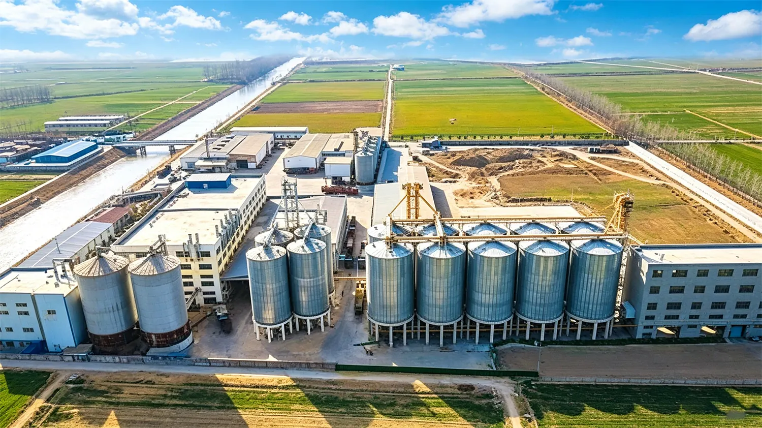
Flat-bottom bins dominate applications requiring large-scale, long-term grain storage. Commercial grain elevators, export terminals, and large farm operations utilize flat-bottom configurations to maximize storage density per square foot of land area. Typical applications include:
- Commercial grain terminals: High-capacity storage (50,000 – 1,000,000+ bushels) with automated loading and unloading systems
- On-farm storage: Medium to large capacity (10,000 – 100,000 bushels) for harvest-time accumulation and seasonal marketing
- Seed processing facilities: Long-term storage requiring controlled atmosphere conditions and minimal handling damage
- Feed mill operations: Raw ingredient storage with extended holding periods between deliveries
Hopper-Bottom Bin Applications
Hopper-bottom bins serve applications where frequent discharge, complete self-emptying, or gravity-fed downstream processing is required. The self-discharge capability reduces labor requirements and eliminates the need for expensive sweep auger systems. Typical applications include:
- Small to medium farm operations: On-farm storage (1,000 – 20,000 bushels) with periodic gravity discharge into trucks or conveyors
- Grain drying systems: Wet grain holding bins positioned above continuous-flow dryers, utilizing gravity feed for consistent throughput
- Seed conditioning plants: Intermediate storage bins where complete discharge prevents cross-contamination between varieties
- Poultry and livestock feed systems: Ingredient bins with gravity discharge into batch mixing equipment
6. Installation and Commissioning of Flat-Bottom vs. Hopper-Bottom Bin
Site Preparation and Foundation Construction
Site preparation begins with geotechnical investigation to determine soil bearing capacity, groundwater level, and frost penetration depth. For flat-bottom bins, the foundation design must account for the total dead load plus the full grain live load, with typical foundation pressures ranging from 2,000 to 4,000 pounds per square foot depending on bin capacity.
The concrete slab for flat-bottom bins requires precise levelness tolerances, typically within ±1/4 inch over the entire diameter, to ensure proper operation of the sweep auger system. Embedded anchor bolts or channel must be positioned accurately to match the bin wall base ring bolt pattern.
Hopper-bottom bin foundations consist of individual spread footings or a continuous ring beam supporting the leg structure. Each footing must be positioned within tight tolerances to ensure proper alignment of the support legs and hopper assembly.
Assembly and Erection Procedures
Flat-bottom bin assembly proceeds from the base ring upward, with wall panels installed in horizontal courses. For bolted construction, each panel is aligned and secured with high-torque bolts, with gasket sealant applied at all joints to ensure weather-tightness. The roof structure is assembled on the ground and lifted into place as a complete unit using hydraulic jacks or cranes.
Hopper-bottom bin assembly requires additional precision due to the hopper geometry. The hopper sections are assembled on the ground and lifted as a complete unit, then secured to the support legs. The cylindrical body is erected on top of the hopper, followed by roof assembly. The entire structure must be plumb and level to ensure proper material flow and structural performance.
7. Maintenance Best Practices for Flat-Bottom vs. Hopper-Bottom Bin
Routine Inspection Protocols
Regular inspection is essential for maintaining structural