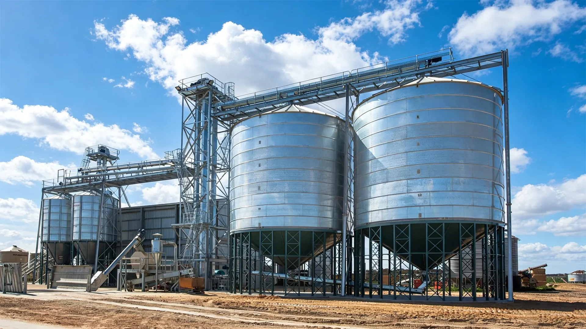
Every grain silo is a cantilever waiting to happen. The shell is thin, the center of gravity is high, and the only thing standing between a full bin and a field of scattered Purchase High-Quality Steel Silo: An Engineer's Guide is a ring of bolts embedded in concrete. Silo anchoring design is where structural engineering meets field practice — and where most failures actually begin.

It is worth stating plainly why this topic deserves more attention than it usually gets. A silo foundation is a one-time, irreversible decision. Once the concrete is poured, the bolt pattern, the embedment depth, the edge distances and the base ring geometry are effectively frozen for the 30 to 50 year service life of the structure. There is no practical way to lengthen an anchor bolt after the fact. Retrofits exist — post-installed adhesive anchors, supplementary hold-down plates, ballast rings, helical piles — but they cost multiples of what a correctly sized cast-in system costs on day one, and they rarely achieve the same reliability. The economics of silo anchoring are brutally asymmetric: a few extra kilograms of Purchase High-Quality Steel Silo: An Engineer's Guide and a slightly deeper embedment cost almost nothing at construction, while a wind-driven anchorage failure destroys the shell, the aeration floor, the sweep auger, the discharge equipment, and often the surrounding concrete — and it does so in under a minute.
This Purchase High-Quality Steel Silo: An Engineer's Guide walks through the full chain of decisions: the loads that actually govern, the bolt sizing and embedment checks, the base ring and anchor chair detailing, grouting, the re-torque protocol that nobody follows properly, code compliance, and the field failures that reveal where the theory breaks down.
Loads That Actually Break Silos: Wind Uplift, Seismic Base Shear, and Overturning Moment Explained
Before you can size a bolt, you have to know what it is being asked to resist. In grain storage, four load families dominate the anchor design conversation, and they rarely act alone.
Wind uplift and the empty-bin problem
Wind creates a pressure distribution over the cylindrical shell and the conical or flat roof. The net result is a vertical force — often upward — plus a horizontal drag force and an overturning moment about the windward base edge. Per ASCE 7, the design uplift combination for a rigid structure is typically 0.9D + 1.0W in LRFD, where D is the dead load of the empty structure and its appurtenances. On a lightweight corrugated or smooth-wall bin, 0.9D is small; a 150 km/h (93 mph) wind can exceed it comfortably. The surplus becomes tension