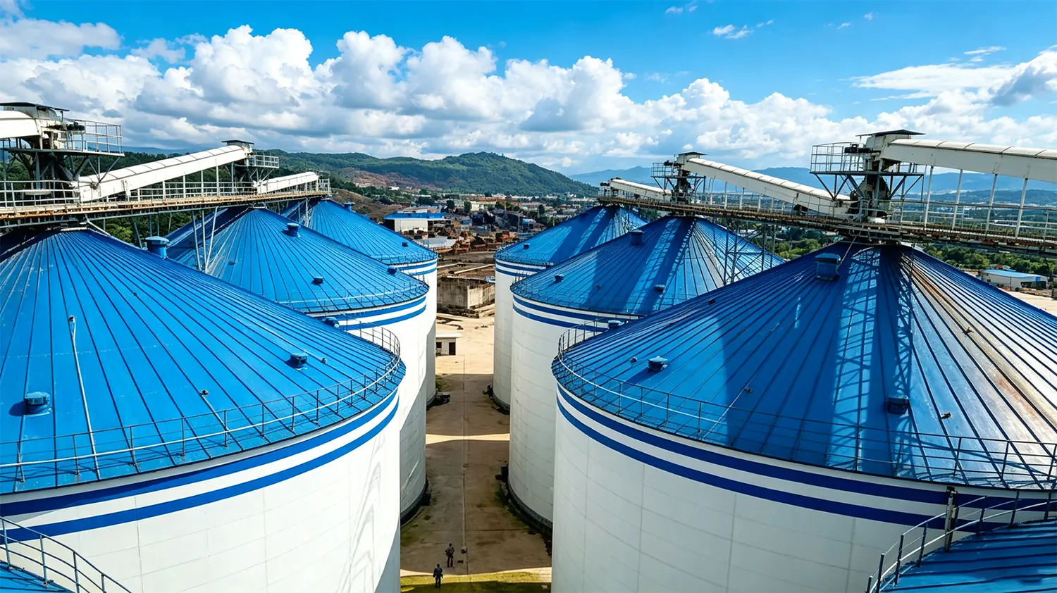
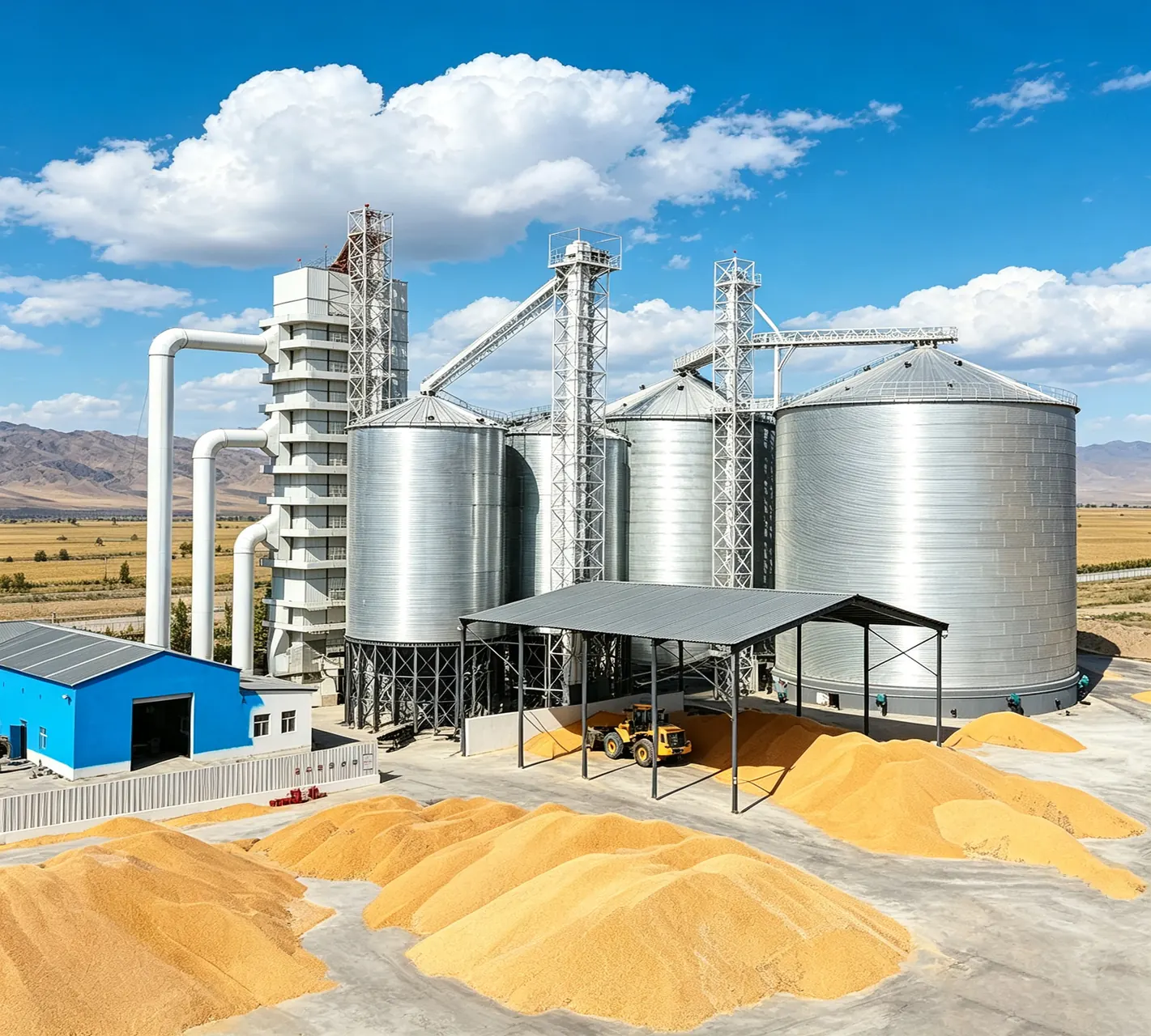
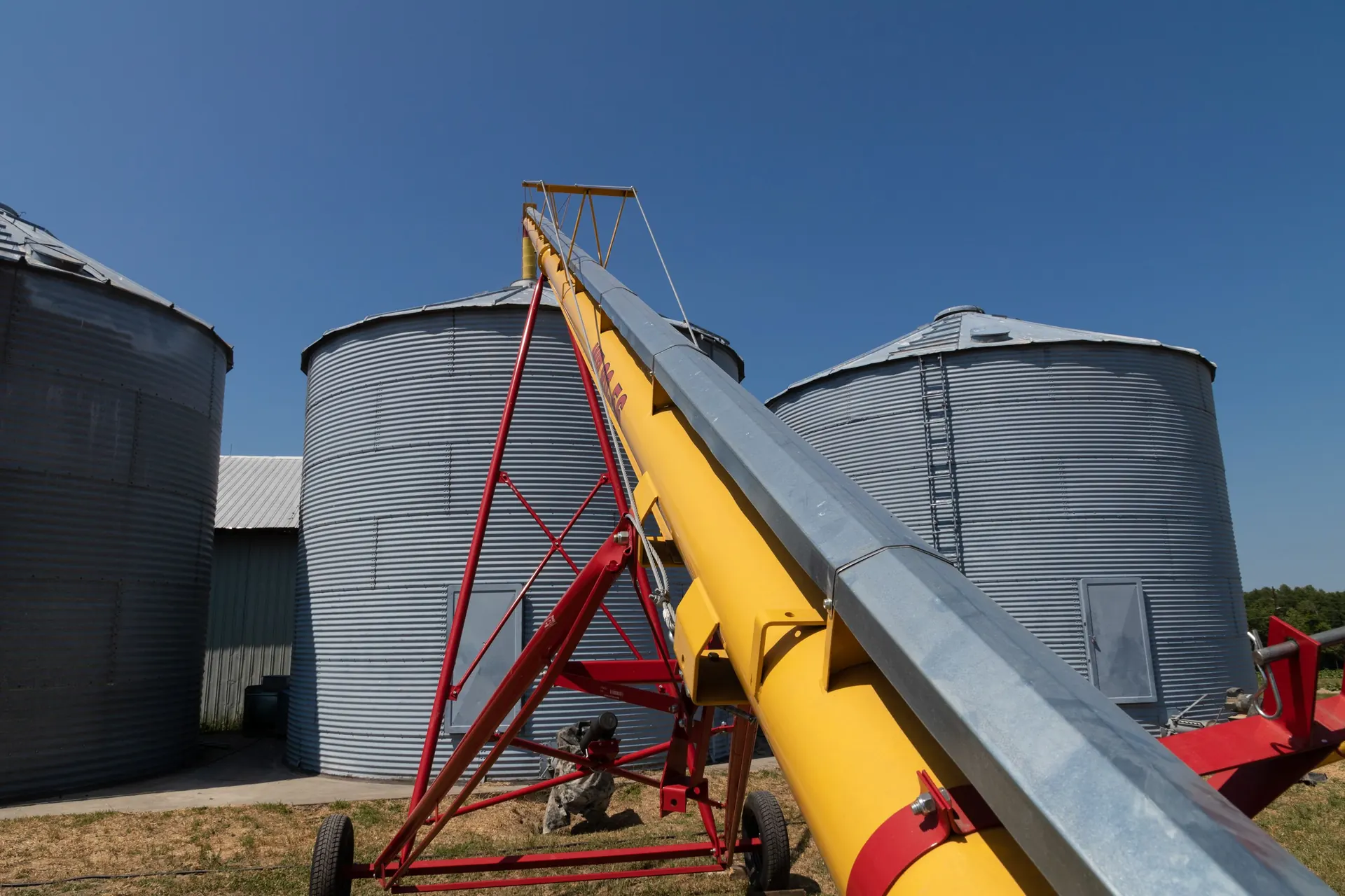
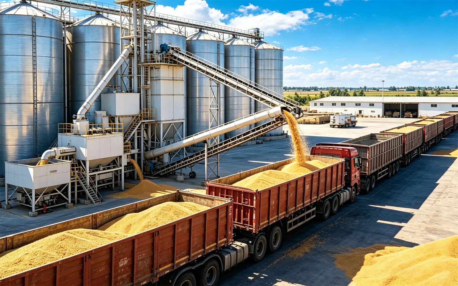
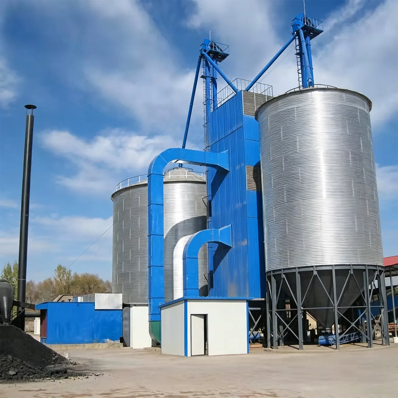
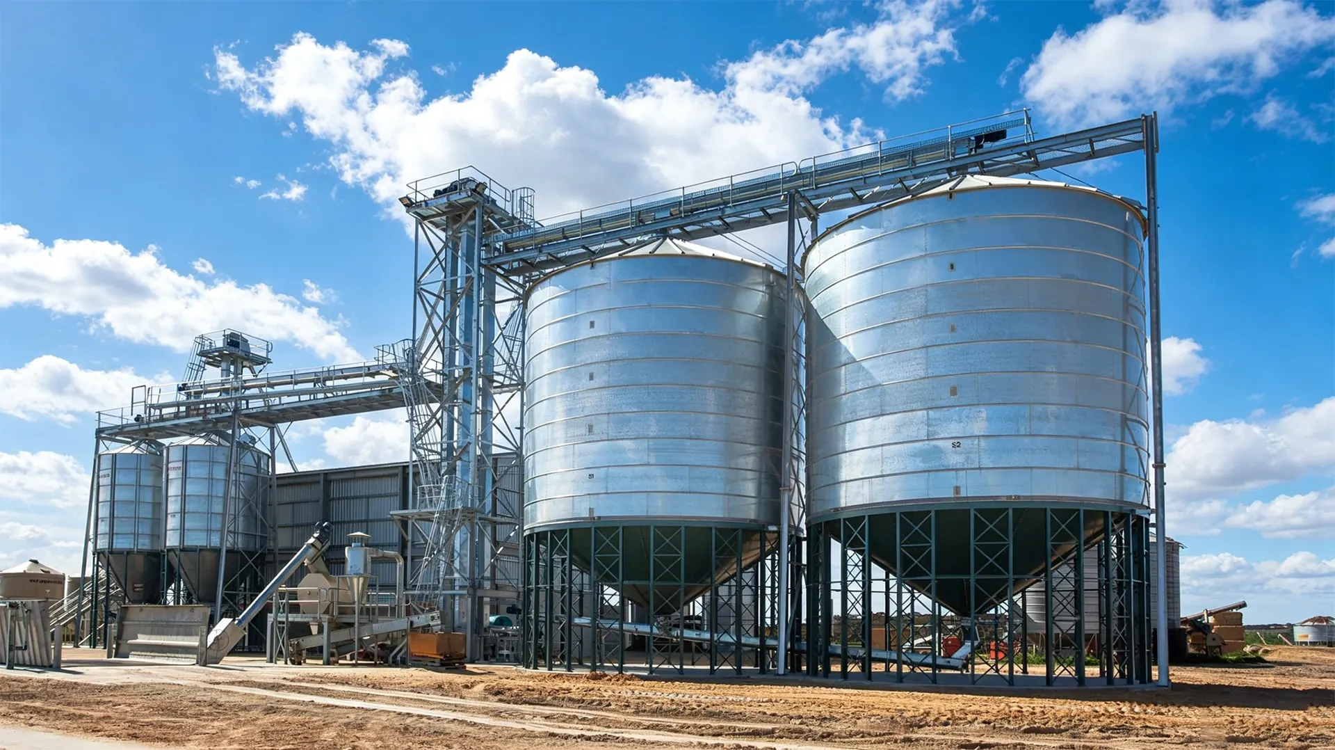
A multi-silo cluster is not simply several Different Types of Silos Used in Cement, Mining & Agr... built side by side — it is a single integrated storage facility where foundations, spacing, conveying, aeration, and erection sequence are designed as one system. Get the cluster geometry and shared infrastructure right, and you gain throughput, grain quality, and a materially lower cost per stored tonne. Get it wrong, and you inherit differential settlement, conveyor bottlenecks, and maintenance corridors too narrow for a service truck.
Multi-Silo Cluster Installation 101: How Cluster Layout Boosts Throughput, Grain Quality, and ROI
A cluster is defined by three things: a common receiving point, a shared transfer system, and a loadout or outbound interface that all Different Types of Silos Used in Cement, Mining & Agr... feed into. Once those three elements exist, the silos themselves become interchangeable storage modules rather than independent facilities. That shift is where the economics change.
What Actually Defines a Cluster
In practice, a cluster begins at roughly three to four Different Types of Silos Used in Cement, Mining & Agr... served by a common bucket elevator and a common drag conveyor gallery. Below that threshold, the cost of shared infrastructure rarely justifies itself, because the elevator and gallery must be sized for peak aggregate flow rather than average flow. Above roughly twelve to sixteen silos, the cluster starts to behave like a terminal, and the design emphasis shifts from silo geometry to traffic management, weighbridge capacity, and outbound loadout rates.
Typical cluster configurations we see in the field include:
- Linear row: simplest layout, single gallery, best for narrow sites with rail or road access along one side.
- Double row (back-to-back): highest storage density per hectare; requires careful design of the central gallery and often a second elevator.
- Block or square cluster: four to nine silos around a central tower; excellent for loadout flexibility, more complex crane access during erection.
- Satellite cluster: one large primary silo with smaller buffer silos for blending, wet grain, or segregated varieties.
Throughput Economics of Cluster Layout
The throughput advantage of a cluster comes from decoupling receiving from loadout. A single standalone silo must stop receiving to fill a truck. A cluster can receive into silo A, transfer through a shared gallery to silo D, and load out of silo G simultaneously. That concurrency is what raises effective intake capacity without adding a second receiving pit.
Design the transfer system for the peak of the sum of simultaneous operations, not for the average. A common failure mode is specifying a drag conveyor at 200 t/h because the elevator is 200 t/h, then discovering that receiving, internal transfer, and loadout can all demand flow at once. The correct approach is to build a simple operating matrix — which silos fill, which discharge, which transfer — and size every conveyor against the worst-case simultaneous row.
Grain Quality and Segregation Benefits
Clusters improve grain quality in ways that are easy to overlook. Segregated storage by moisture, variety, or protein allows you to dry only the wet parcels, blend to specification at loadout, and hold conditioned grain undisturbed for months. In a cluster, that segregation costs almost nothing because each silo is a discrete bin with its own aeration control and its own temperature monitoring.
Quality also benefits from shorter residence times in the transfer system. Long, high-capacity drag conveyors running partially full create more grain damage than short runs running at design capacity. Keep transfer distances compact by arranging the cluster so the elevator sits at the centroid of storage, not at one end.

Site Selection and Geotechnical Engineering for Multi-Silo Clusters
Silo clusters concentrate load in a way that single silos do not. Six 5,000-tonne silos on a compact footprint can impose combined foundation loads exceeding 60,000 kN on a relatively small area, plus the dynamic surcharge of truck traffic and the lateral loads from wind acting on a group of closely spaced cylinders. The geotechnical investigation must be scoped for the cluster, not for one bin.
Subsurface Investigation Scope
As a minimum, plan one borehole per two silos plus one at the elevator tower and one at the receiving pit, taken to a depth of at least twice the loaded width of the largest foundation. Standard penetration tests or cone penetration tests should be paired with laboratory consolidation testing on cohesive layers. For soft clays and organic soils, a consolidation settlement analysis under the full cluster load is mandatory — the settlement bowl from a cluster extends far beyond the footprint and can affect neighbouring structures, drainage grades, and even the adjacent highway.
Target allowable bearing pressures of 150–300 kPa for competent granular soils. Below 100 kPa, expect ground improvement or a piled solution. Where rock is shallow, anchor the ring wall into rock and design for the resulting stress concentrations rather than assuming a uniform bearing distribution.
Drainage, Stormwater, and Frost Depth
Cluster sites fail on drainage more often than on bearing capacity. The roof area of six 20 m diameter silos is roughly 1,900 m², and every drop of that water lands inside the cluster footprint. Design roof drainage to discharge outward, away from foundations, and never into the space between silos.
Grade the apron at 1.5–2.0% away from foundations toward perimeter swales. Set finished floor level a minimum of 300 mm above the surrounding graded surface and confirm that level against the local 100-year flood elevation. Foundation depth must extend below frost penetration — typically 0.9–1.5 m in temperate regions, deeper in continental climates — with a compacted granular backfill collar around the ring wall to intercept surface water.
Traffic Flow and Circulation Geometry
Design truck circulation before you place the silos, because you cannot move a foundation later. A single-unit grain truck with trailer needs roughly a 27 m turning radius at the outer path and a running lane of at least 4.5 m. Provide a separate inbound lane and outbound lane at the receiving pit wherever daily intake exceeds 1,500 tonnes, and locate the weighbridge so that no loaded truck has to cross an empty truck's path.
Keep a minimum 6 m clear circulation corridor around the outside of the cluster for service vehicles, fire access, and future fan or duct replacement. Inside the cluster, provide a dedicated maintenance route of at least 1.2 m between adjacent silo shells where personnel must access aeration ducts, level indicators, or side-wall inspection doors.
Foundation Design for Dense Silo Clusters: Ring Walls, Pile Caps, and Differential Settlement
Foundation design for a cluster is fundamentally a differential settlement problem. Each silo can tolerate a small amount of absolute settlement; what it cannot tolerate is settling differently from its neighbour or tilting as a rigid body, because both distort the shell, bind the discharge equipment, and open joints in bolted construction.
Ring Wall and Slab Foundations
For flat-bottom silos on competent soil, a reinforced concrete ring wall under the shell perimeter, combined with an interior slab, is the most economical solution. The ring wall carries the shell loads, the slab carries the grain load and transfers it to the soil. Typical ring wall widths run 400–700 mm with a minimum concrete grade of C30/37 (or 4,000 psi equivalent), reinforced to resist hoop tension and local bending under the shell.
For hopper-bottom or elevated silos, a grid of columns on isolated pad footings or a piled cap beam system is more appropriate. The critical detail is tying the individual footings together with grade beams so the cluster behaves as a single rigid system rather than a series of independent supports.
Pile Caps and Differential Settlement Control
Where soft strata extend below 6–8 m, piled foundations with a common pile cap per silo are standard. In dense clusters, consider a continuous piled raft spanning two or more silos — it costs more in concrete but virtually eliminates relative settlement between adjacent bins and simplifies the gallery support structure.
Set settlement criteria explicitly in the foundation specification:
- Total settlement of any silo: typically limited to 25–50 mm.
- Differential settlement across the silo diameter: limited to 1/500 of diameter (roughly 40 mm for a 20 m silo).
- Relative settlement between adjacent silos: limited to 15–25 mm.
- Differential settlement between a silo and the connected elevator tower: limited to 10 mm, with slip joints or flexible connections in the transfer chutes.
| Foundation Type | Best Suited Soil | Relative Cost | Key Advantage |
|---|---|---|---|
| Ring wall + interior slab | Competent granular, N > 15 | Low | Economical, fast to build |
| Reinforced raft / mat | Variable or layered soils | Medium | Redistributes load, tolerant of soft pockets |
| Pile cap with driven or bored piles | Soft clay, fill, high water table | High | Controls settlement precisely |
| Continuous piled raft (multi-silo) | Poor soils under dense clusters | Highest | Near-eliminates inter-silo differential movement |
| Ground improvement + ring wall | Loose sands, silts | Medium | Reduces foundation size and cost |

Cluster Spacing and Structural Interaction: Wind Loads, Thermal Expansion, and Maintenance Access Corridors
Spacing is the single most consequential layout decision in a cluster. It determines whether you can erect the silos, whether you can maintain them, and how the group responds to wind.
Minimum Spacing Recommendations
Practical minimum clear spacing between adjacent steel silo shells is 0.5 m for small bins under 8 m diameter, rising to 1.0–1.5 m