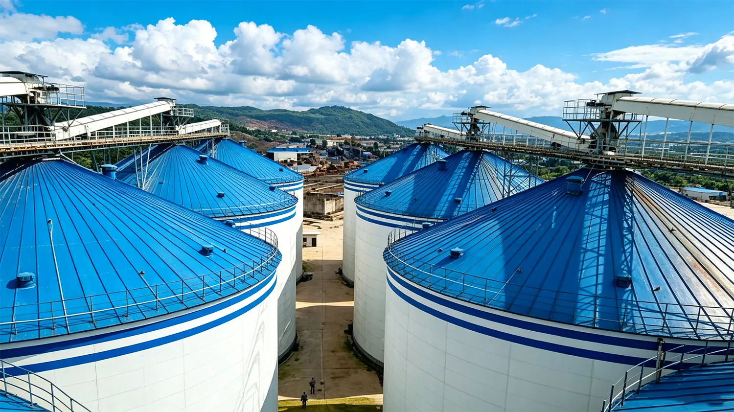
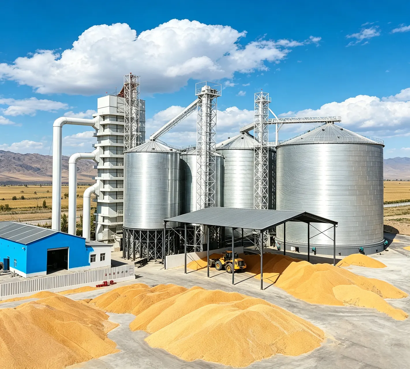
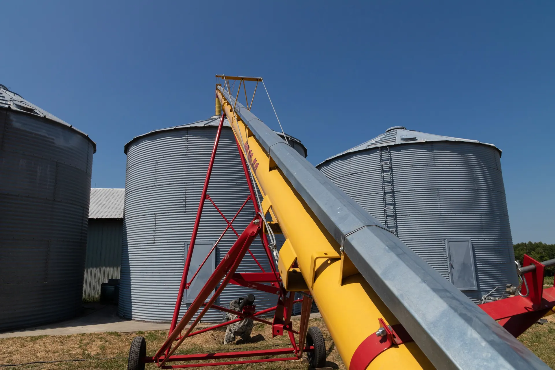
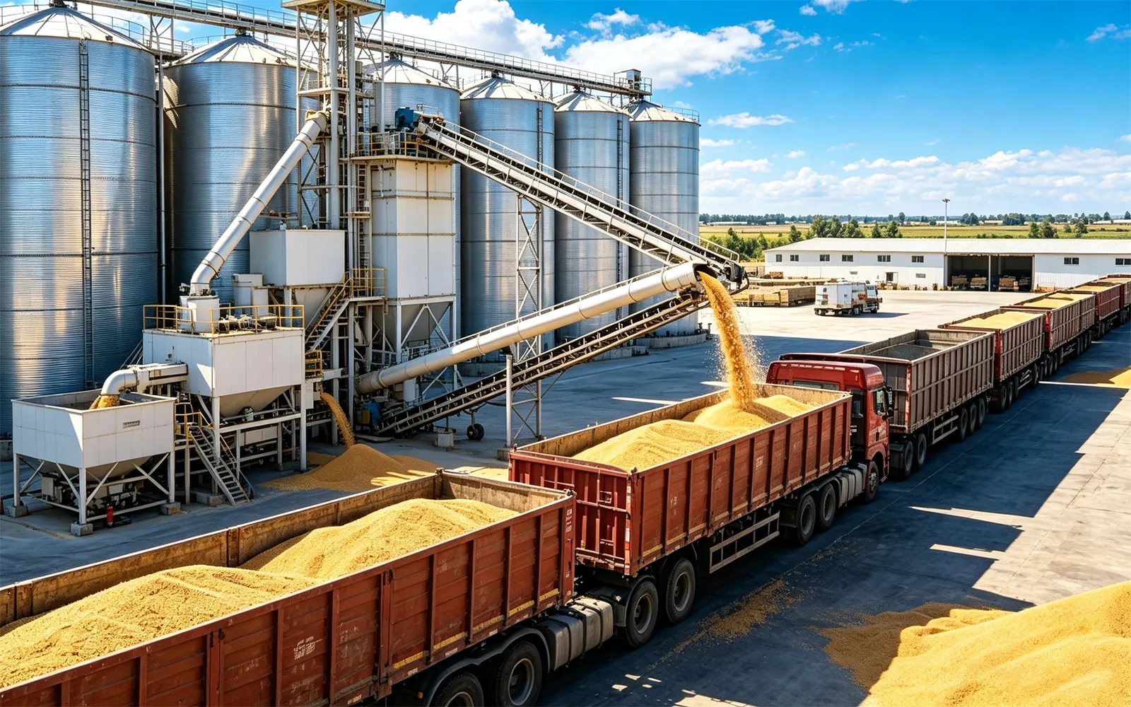
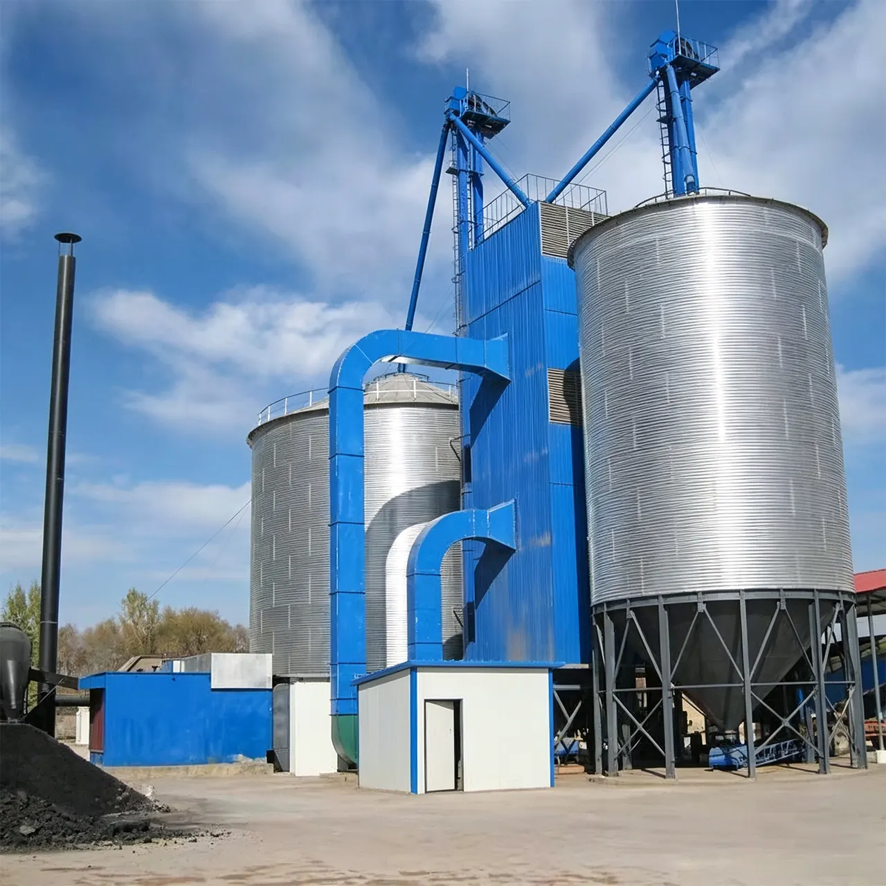
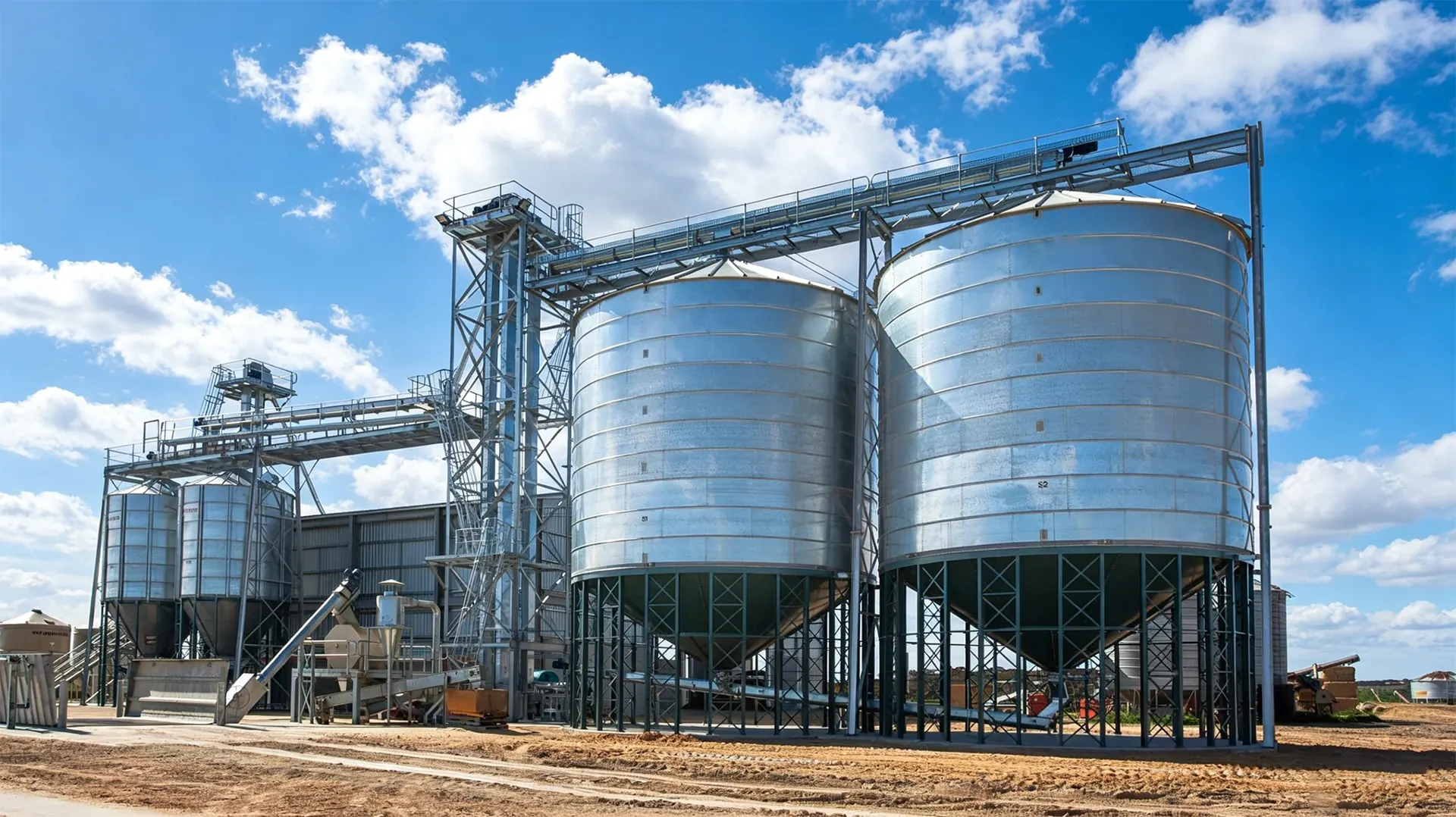
Adding a silo to a working Dust Explosion Prevention in Grain Storage Facilities: En... facility is never just a construction project — it is a surgical operation performed on a system that must keep receiving, drying, and shipping grain throughout. Silo tie-in installation is the discipline of joining new Purchase High-Quality Steel Silo: An Engineer's Guide, new spouting, and new controls to an existing facility without breaking capacity, airflow balance, or code compliance. This guide walks through the engineering, mechanical, and commissioning decisions that separate a smooth brownfield expansion from a season-long headache.
Silo Tie-In Installation Explained: What It Takes to Connect a New Silo to a Live Grain System
A silo tie-in is the complete interface package that lets a new bin function as part of the existing grain flow rather than as an isolated structure. That package includes the receiving path into the new bin, the discharge path out of it, the structural connection to foundations and catwalks, the aeration and ventilation connections, the dust and Dust Explosion Prevention in Grain Storage Facilities: En...-safety provisions, and the electrical and control interlocks that tell the plant's automation system the new bin exists.
The defining constraint is that the host facility keeps operating. Grain is still arriving by truck, the dryer is still running, and the shipping schedule has not changed. Every tie-in decision therefore has to answer two questions: does it work hydraulically and mechanically, and can it be executed in the available outage window without starving the rest of the plant?

Pre-Tie-In Engineering Survey: Elevations, Capacities, and Site Conditions That Prevent Rework
The survey is where the project is won or lost. A proper pre-tie-in survey captures more than a site plan; it documents the as-built condition of a facility that may have been modified three times since the original drawings were issued.
Establishing the Elevation and Capacity Baseline
Every tie-in begins with a benchmarked elevation survey tied to a permanent site datum. The survey must record the top of the existing bucket elevator head, the invert and discharge elevations of every drag conveyor and distributor, the finished floor elevation at each bin, and the centerline coordinates of existing spouting runs. As-built drawings are a starting point, not a reference — field verification with a total station or laser level is mandatory.
Capacity matching follows the elevation work. The new bin's fill rate must be compatible with the existing elevator's throughput, and its discharge rate must be compatible with the receiving conveyor. A bin that can be filled in four hours but takes fourteen to empty creates a queue problem that no amount of automation will solve.
Site Conditions and Brownfield Constraints
Underground utilities, existing foundations, buried conduit, and drainage swales all constrain where a new bin can stand. Geotechnical borings at the new bin location should be compared against the original soil report for the host facility, because differential behavior between old and new foundations is the single most common structural complaint after commissioning.
Structural Tie-In Essentials: Foundations, Anchor Bolts, and Differential Settlement at the Connection
Foundations and Anchor Bolt Compatibility
New silos typically arrive with a proprietary anchor bolt pattern. Where a tie-in connects to an existing foundation, a transition ring or adapter plate is often required, and the bolts must be sized for the governing uplift and shear case, not the nominal wind case. Anchor bolts should be set with templates, verified for projection and plumb before grouting, and torqued in a documented star pattern after the bin shell is plumbed. Non-shrink grout with a minimum 7,000 psi compressive strength is standard practice under base plates.
Differential Settlement at the Connection
When a new bin shares a catwalk, spouting bridge, or interconnecting platform with an older structure, differential settlement becomes a design load. The connection detail should permit vertical movement of several millimeters without transferring load into the spouting. Slotted connections, expansion joints in spouting, and flexible boots at transition points are the practical answers. A rigid, fully welded spout between two structures with different settlement histories will crack, buckle, or pull apart.

The Elevation Equation: How Spouting Slope, Transition Chutes, and Lift Height Drive Tie-In Design
Grain does not negotiate. Spouting slope and transition geometry determine whether a tie-in flows reliably for the next twenty years or plugs on the first wet harvest.
Spouting Slope and Transition Chutes
Gravity spouting in grain service is normally designed at a minimum of 45 degrees from horizontal, with 50–55 degrees preferred for corn, high-moisture grain, and any material with fines content. Transition chutes — the short, angled sections where flow changes direction — should be at least as steep as the main run and should avoid abrupt area changes that cause grain to stall.
| Material / Condition | Minimum Slope | Preferred Slope | Notes |
|---|---|---|---|
| Dry corn, wheat, soybeans | 45° | 50° | Steeper for long runs and multiple transitions |
| High-moisture grain (pre-drying) | 50° | 55–60° | Increased cohesion and bridging risk |
| Grain with high fines or trash | 50° | 55° | Fines reduce flowability and promote build-up |
| Transition chutes at direction changes | 50° | 55–60° | Never shallower than the upstream run |
Lift Height and Headroom
Adding a bin almost always changes the required lift height somewhere in the system. If the new bin's fill spout must clear an existing catwalk or conveyor, the elevator head may need to be raised — a significant structural and mechanical change. Surveying the actual headroom before design, rather than after fabrication, prevents the painful discovery that a spout will not clear a handrail by 200 mm.
Mechanical Tie-In: Matching Distributors, Drag Conveyors, and Bucket Elevator Capacity to the New Silo
The mechanical tie-in is where throughput math meets physical reality. The bucket elevator is normally the bottleneck: its capacity, belt speed, and boot configuration set the maximum fill rate for the entire bin cluster. Adding a bin to an elevator already running near its rated capacity will require either a larger leg, a second elevator, or a revised operating philosophy in which bins are filled in sequence rather than simultaneously.
Distributors must be sized for the total number of outlets and the required fill rate per bin, and their inlet must accept the elevator discharge without choking. Drag conveyors need to be checked for the additional length, the added start-up torque from a longer chain, and the discharge point geometry into the new bin's inlet. Slide gates, diverter valves, and rotary valves should be specified for the grain's bulk density and for wear service, with replaceable liners in high-wear zones.
Aeration and Airflow Tie-In: Ducting, Fan Sizing, and Static Pressure Balance Across Multiple Bins
Aeration tie-ins are frequently underestimated because each bin looks independent. In practice, a shared fan plenum or manifold serving multiple bins behaves as a single hydraulic network, and static pressure balance determines which bin actually receives the airflow.
Design airflow rates for stored grain aeration generally fall between 0.05 and 0.5 CFM per bushel depending on the objective — maintenance aeration sits at the low end, while cooling wet grain in a bin requires substantially more. Fan sizing must be based on the system curve of the entire duct network, not the bin alone. Where a single fan serves multiple bins, motorized dampers and interlocked controls prevent air from short-circuiting through an empty bin. Duct transitions should be gradual, with total equivalent length calculated including elbows, and flexible connections at bin penetrations to isolate vibration.

Dust Control, Venting, and Explosion Safety: NFPA-Compliant Tie-Ins for Grain Handling Systems
Any tie-in that adds grain handling capacity also adds dust generation and a new potential ignition or propagation path. In the United States, grain handling facilities are governed by NFPA 61 for dust hazard management, NFPA 652 for fundamentals of combustible dust, and NFPA 68 and 69 for explosion venting, prevention, and isolation.
Practical tie-in provisions include:
- Explosion venting on the new bin sized to the bin volume and the material's Kst and Pmax, with vents directed away from occupied areas and walkways.
- Isolation devices — rotary valves, flap valves, or chemical barriers — between the new bin and the shared elevator or dust collector so a deflagration cannot propagate into the existing system.
- Aspiration at transfer points, sized for the new dust load and connected to a dust collector with adequate air-to-cloth ratio and a rated explosion vent.
- Bonding and grounding of all new spouting, bins, and ductwork, verified with resistance measurements documented at commissioning.
- Updated dust hazard analysis (DHA) covering the modified system, not just the new equipment.
Electrical, Controls, and Interlock Tie-In: Level Sensors, PLC Logic, and SCADA Integration
Control integration is often the last item scheduled and the first item to delay start-up. The new bin needs level indication — typically a combination of a continuous sensor such as a radar or plumb-bob unit plus high- and low-level switches for alarm and interlock functions. Bin temperature cables and aeration fan status should be wired into the same control architecture.
PLC logic must be updated, not merely appended. Interlocks that stop upstream equipment when a downstream conveyor stops need to recognize the new bin as a valid destination. New motor starters, VFD parameters, and safety circuits must be coordinated with the existing control voltage and network protocol. Where the plant runs SCADA, the new bin requires HMI graphics, alarm setpoints, trend history, and historian tags. Testing every interlock in simulation before the first grain enters the bin is far cheaper than discovering a missing permissive at 2 a.m. during harvest.
Hot Tie-In vs. Shutdown Tie-In: Bypass Strategies That Keep the Facility Running During Installation
The choice between a hot tie-in and a shutdown tie-in shapes the entire project schedule. A hot tie-in keeps the facility operational by building bypass paths and sequencing work into short, isolated windows. A shutdown tie-in takes the affected portion of the plant offline for a defined period, which is faster per unit of work but carries a real cost in lost receiving or shipping capacity.
| Factor | Hot Tie-In | Shutdown Tie-In |
|---|---|---|
| Facility operation | Continuous, with bypass routing | Affected systems offline |
| Total duration | Longer, more site visits | Shorter, concentrated |
| Engineering effort | Higher — bypass and temporary supports required | Lower |
| Safety exposure | Higher — work near live equipment | Lower — isolated and locked out |
| Best used when | Harvest or shipping commitments cannot move | Off-season window is available |
Most successful brownfield projects use a hybrid: long-lead structural and foundation work proceeds hot, while the final spouting cuts, electrical changeovers, and control cut-ins are compressed into a planned outage.