In a cement grinding circuit, the mill and the classifier form a single, tightly coupled system. The mill reduces clinker, gypsum and supplementary cementitious materials to a workable particle size distribution; the classifier decides which particles are finished product and which must be returned for another pass. When either component drifts out of specification — a worn liner profile, a distorted shell, an eroded rotor blade, a mis-set Ventilation Fan Failure: Diagnosis and Repair Guide for G... vane — the consequences appear as higher specific energy consumption, unstable Blaine fineness, excessive circulating load, and cement that either sets too fast or develops strength too slowly.
The problem is that these drifts happen slowly. A liner loses a millimetre or two of thickness per thousand operating hours. A classifier rotor tip clearance opens up by a few millimetres per year. Because the change is gradual, the plant rarely notices until power consumption has risen by 3–5 kWh/t or the residue on the 45 µm sieve has moved outside the control band. Regular, structured measurement is the only reliable way to detect these changes before they translate into lost margin.
This Ventilation Fan Failure: Diagnosis and Repair Guide for G... covers what to measure, how to measure it, which instruments to use, and how to interpret the results. It is written for maintenance engineers, process engineers and grinding circuit supervisors who need a practical, shutdown-friendly measurement programme rather than a theoretical treatment.
Why Measurement Discipline Pays Off
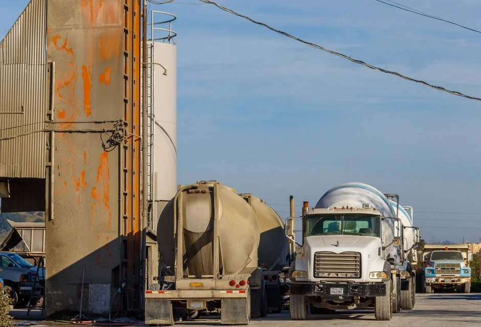
Grinding typically accounts for 30–50% of the electrical energy consumed in an integrated cement plant, and the finish mill alone can draw 25–40 kWh per tonne of cement. A grinding circuit operating 5% below its optimum geometry and classifier setting can easily waste 1.5–2.5 kWh/t. On a 1.5 million tonne per year plant, that is between 2.2 and 3.7 GWh of avoidable consumption annually — plus the associated cost of unstable product quality and increased reject rates at the packing plant.
Measurement also protects capital. Extending the life of a mill shell, a trunnion, or a classifier rotor by even one campaign between replacements is worth far more than the cost of the inspection programme that made it possible.
Measuring the Cement Mill
1. Shell Geometry and Out-of-Roundness
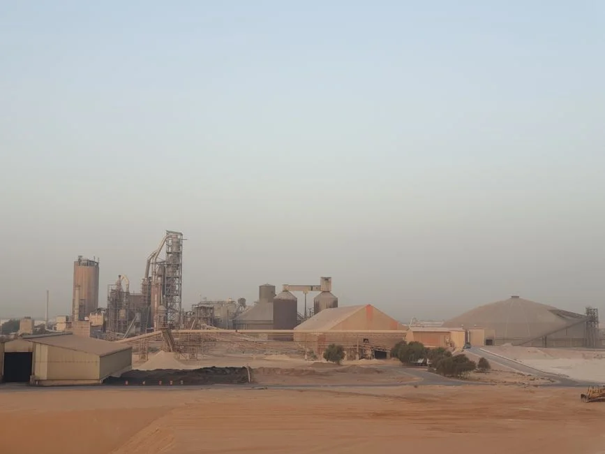
The mill shell is the reference datum for everything else. Measure the internal diameter at a minimum of four stations along the grinding length (inlet, first compartment, diaphragm zone, second compartment, outlet) and at four angular positions per station (0°, 90°, 180°, 270°). Record the values in a table and calculate the out-of-roundness at each station as the difference between the maximum and minimum diameter.
Acceptable out-of-roundness is generally below 0.1–0.2% of the nominal diameter. A 4.6 m mill should therefore stay within roughly 4.6–9.2 mm. Larger deviations indicate shell distortion, differential foundation settlement, or uneven support conditions, and they will cause erratic media trajectory, accelerated liner wear on one side, and vibration that shortens gearbox life.
For high-accuracy work, use a portable laser tracker or a total station referenced to the mill axis. For routine checks, a large internal micrometer or a purpose-built diameter gauge is adequate, provided the same operator and the same reference points are used every time.
2. Effective Grinding Length and Compartment Lengths
Effective grinding length (EGL) is measured between the face of the inlet end liner and the face of the outlet end liner — not between the shell flanges. Compartment lengths are measured from liner face to liner face. Always state whether a length was measured with new liners or worn liners, because a 60 mm liner loss in each of two compartments changes the EGL by 120 mm, which is enough to shift the residence time and the grindability balance between compartments.
3. Liner Thickness and Profile
Liners do more than protect the shell; they control the media trajectory. Measure liner thickness with an ultrasonic thickness gauge at a grid of points — typically three circumferential positions per row and every second or third row. Record:
- Remaining thickness versus original thickness (wear percentage)
- Plate height or step height, which governs the lift of the grinding media
- Bolt condition, bolt torque and any evidence of liner movement
- Localised wear patterns — a single heavily worn zone often points to a feed-end or diaphragm-related flow problem
In the first compartment, classifying liners or step liners should be checked for plate height loss. Once the step height has dropped by more than about 30% of its original value, the media charge is no longer being lifted correctly and the mill loses impact grinding capacity.
4. Diaphragm and Transfer Diaphragm
Measure the slot width, slot length, open area percentage, and the radial and central clearances of the diaphragm. Slot wear and blinding are two of the most common, least-detected causes of poor mill performance. Record the number of blocked slots and the average slot width in each quadrant. A diaphragm that has opened up by 20% will pass coarse material into the second compartment, forcing the classifying liners to do work they were never designed for.
5. Grinding Media Charge
Media measurement includes the filling degree, the top ball size, and the size distribution in each compartment. The filling degree is normally calculated from the distance between the charge surface and the mill centreline while the mill is stopped, or from the mill power draw under known conditions. Sample the charge and sieve it to establish the actual grading, then compare it against the design curve.
Also calculate the critical speed and the actual operating speed as a percentage of critical:
nc = 42.3 / √D
where nc is critical speed in rpm and D is the internal diameter in metres. Most cement mills run at 70–78% of critical speed. If the percentage has drifted because the effective diameter has increased through liner wear, the media trajectory has changed too.
6. Mechanical and Process Parameters
- Mill power draw — record kW at steady state, corrected for media load and filling degree.
- Specific energy — kWh per tonne of finished cement, the single most important performance indicator.
- Trunnion and journal condition — journal diameter, ovality, surface finish and bearing clearance.
- Girth gear and pinion — radial and axial runout, backlash, root clearance and tooth contact pattern.
- Ventilation — air velocity at the mill inlet and outlet ducts, typically 1.0–1.5 m/s in the mill body, plus pressure drop across the mill.
- Temperatures — inlet and outlet material and gas temperatures,