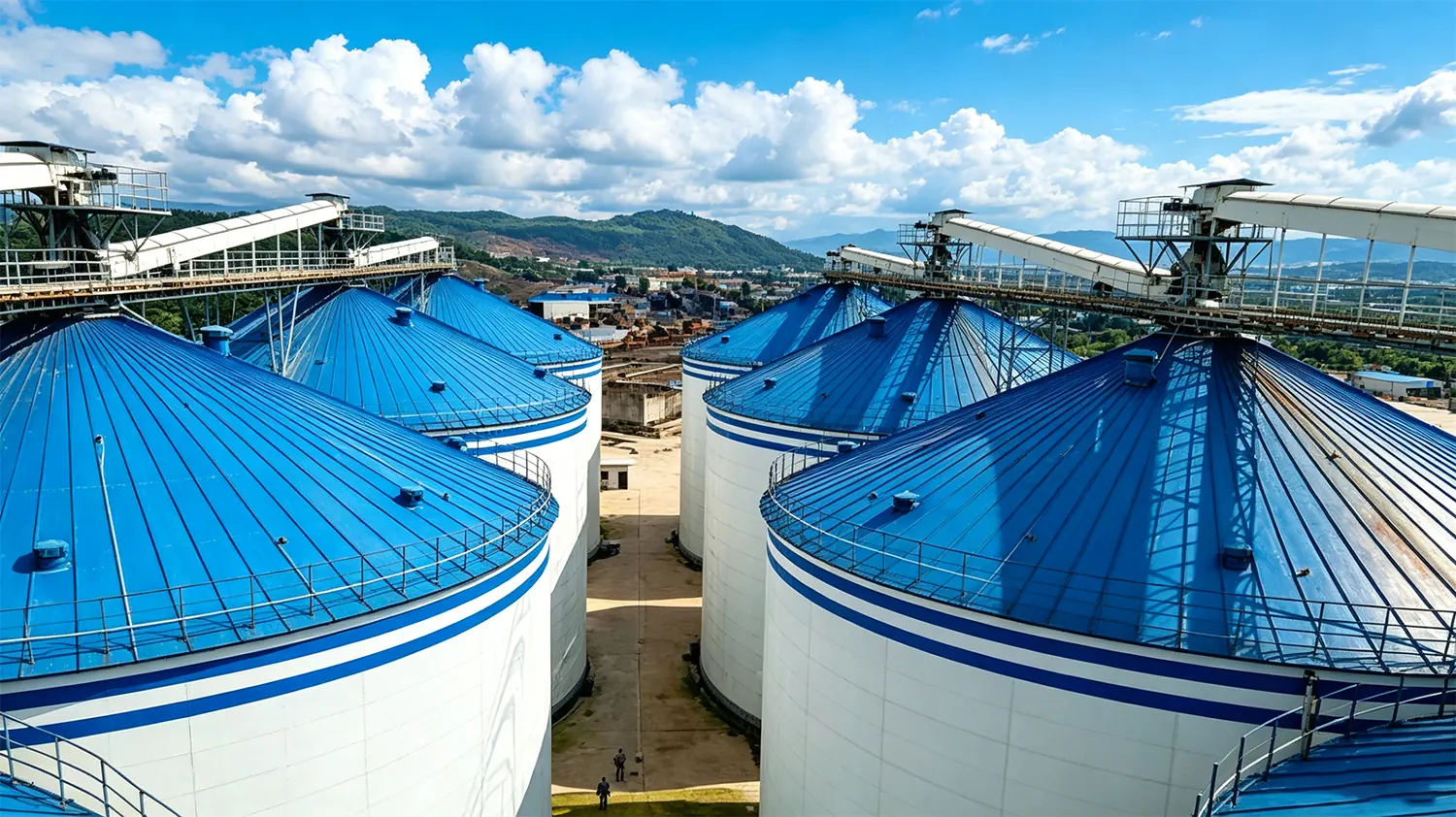
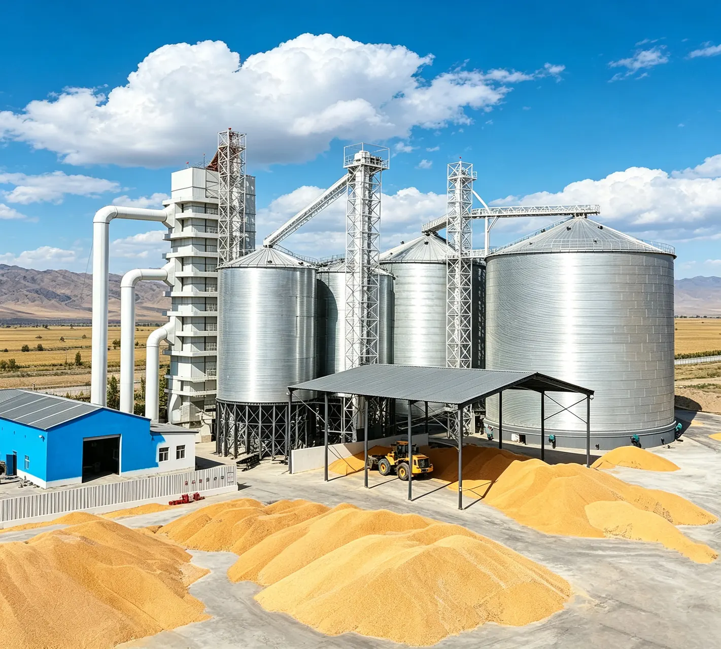
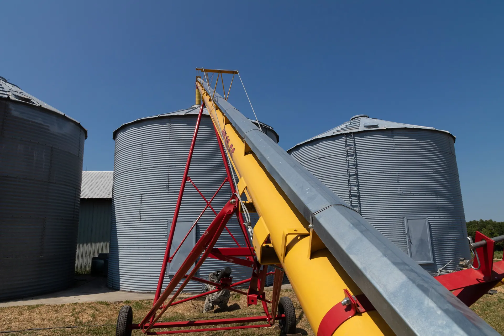
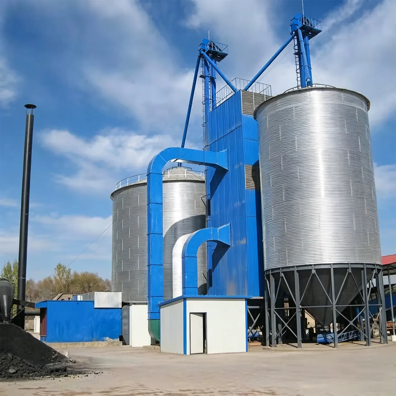
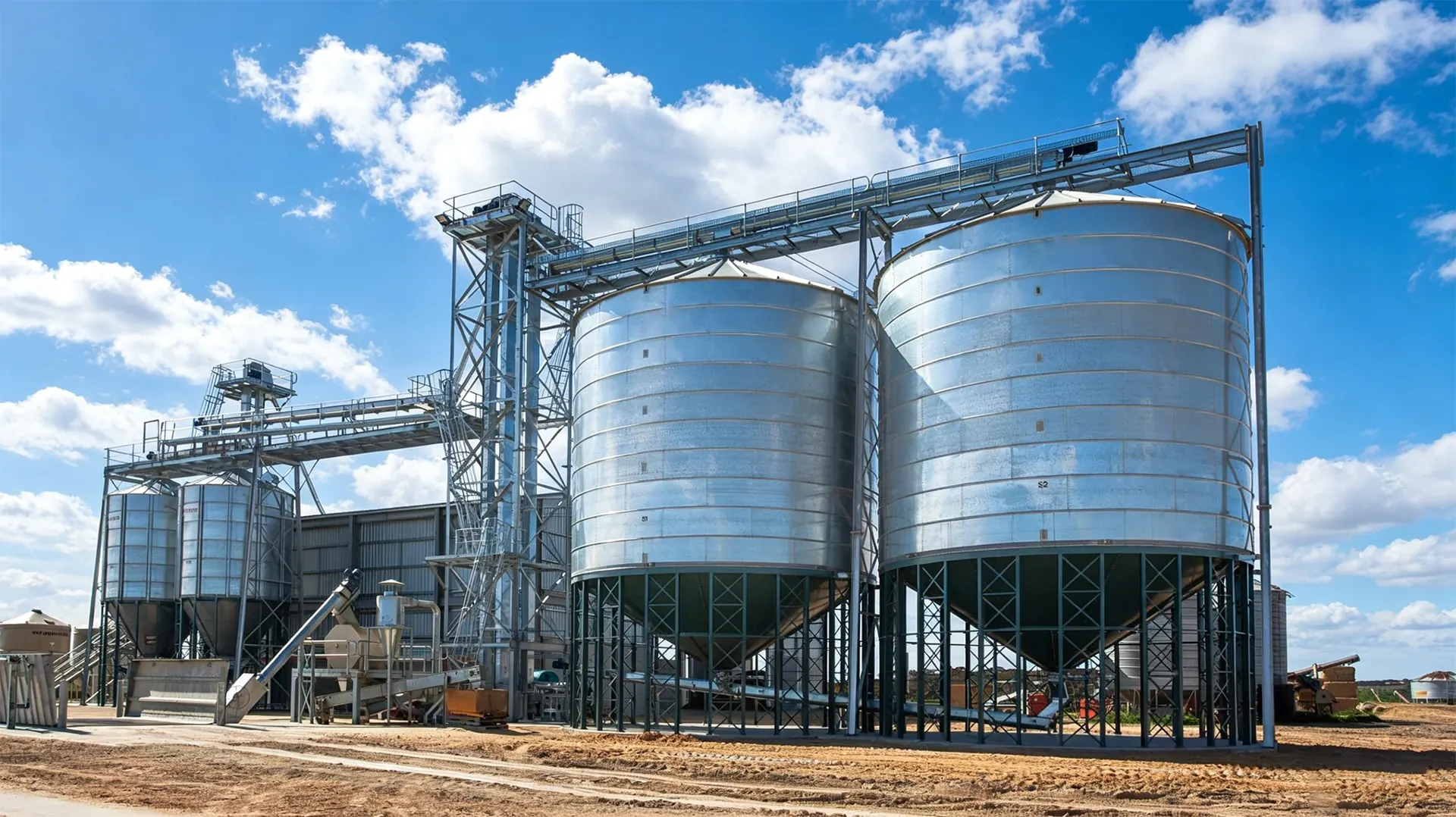
Insulation cladding installation is the single most cost-effective intervention available to grain storage operators who need to stop condensation, hold grain quality through seasonal swings, and extend the service life of bins, Different Types of Silos Used in Cement, Mining & Agr..., and drying systems. Get the detailing right and the asset performs for 30 years; get the laps, fasteners, or penetrations wrong and you will be repairing corrosion and spoiled grain within three seasons.
Key Engineering Takeaway
A Purchase High-Quality Steel Silo: An Engineer's Guide sheet expands and contracts at approximately 0.012 mm per metre per °C. On a 20 m silo wall facing a 50 °C annual surface temperature swing, that is roughly 12 mm of movement that must be absorbed by correctly positioned expansion joints — not resisted by over-tightened fasteners. Thermal movement, not wind, is the most common cause of premature cladding failure on wide-span grain roofs.
Why Insulation Cladding Matters More Than You Think: Condensation Control, Thermal Efficiency, and Structural Longevity
Most operators approach cladding as a weatherproofing exercise. In grain storage, it is fundamentally a moisture management exercise. Bare Purchase High-Quality Steel Silo: An Engineer's Guide silo walls and roofs behave as highly efficient thermal bridges. On a cool autumn night, the internal steel surface can sit 4–8 °C below the interstitial air temperature. When that surface drops below the dew point of the headspace air — which is common during the diurnal cycle after a warm day's aeration — condensation forms directly above the grain mass. Water then drips onto the grain surface, creating the classic caking, crusting, and mould pocket that leads to rejection loads.
Insulation cladding addresses this in three ways simultaneously:
- Thermal break: Continuous insulation raises the internal surface temperature above the dew point, eliminating the cold surface that drives condensation.
- Vapour control: A correctly positioned vapour control layer, combined with sealed laps, keeps moist internal air out of the insulation cavity, protecting the thermal performance of the insulation itself.
- Corrosion protection: A drained and ventilated cavity allows incidental moisture to escape rather than pooling against the structural steel — the mechanism behind most silo wall perforation.
There is also a genuine energy dividend. Insulated drying bins and silos hold plenum temperatures more stably, reduce heater cycling, and cut aeration runtime. In continuous-flow drying systems, insulated plenums and ductwork reduce heat loss between the burner and the grain column, which directly improves drying efficiency and grain quality.

Cladding Materials and Profiles Compared: Trapezoidal, Standing Seam, Micro-Rib, and Insulated Sandwich Panels
Profile selection drives the whole installation sequence. Each system has a different lap strategy, fixing density, and tolerance to thermal movement.
| Profile Type | Typical Use on Grain Assets | Lap Strategy | Fixing Density | Thermal Movement Tolerance |
|---|---|---|---|---|
| Trapezoidal (33/1000, 35/1000) | Silo walls, duct covers, side cladding | One-rib side lap, sealed with butyl tape | High — 300 mm at edges, 450–500 mm field | Moderate; requires stitch screws at laps |
| Standing seam | Wide-span silo roofs, large drying buildings | Mechanically seamed, no through-fasteners in the pan | Low — concealed clips | Excellent; clips allow longitudinal slide |
| Micro-rib / corrugated liner | Internal liners, smooth-face applications | Single or double rib lap | Medium | Good; low profile handles small movements |
| Insulated sandwich panel (PIR/PUR/mineral wool core) | Flat-sided silos, dryer buildings, control rooms | Interlocking tongue-and-groove with factory seals | Concealed or face-fixed, 500 mm typical | Good, provided panel joints are not over-restrained |
For grain-specific environments, substrate specification matters as much as profile. Galvanised coatings in the Z275 or AZ150 range, or coil-coated steel with a PVDF or polyester finish, deliver materially longer service life in dust-laden, fumigant-exposed conditions. On ammonia-rich sites — fertiliser blending areas, for example — stainless steel fasteners in A2 or A4 grade are non-negotiable.
Pre-Installation Site Survey: Substrate Condition, Moisture Mapping, and Thermal Bridging Audit
No cladding should be installed before a documented survey. Three checks matter above all others.
Substrate Condition
Assess the existing structure for section loss, coating breakdown, and fastener corrosion. Hammer-test or ultrasonic-thickness-test the silo wall at representative elevations. Any substrate below 80% of original section should be repaired or reinforced before cladding is applied — you are encapsulating the structure, and hidden deterioration becomes expensive deterioration.
Moisture Mapping
Use a calibrated pin or capacitance moisture meter on the substrate and on adjacent concrete plinths. Record readings on a grid and mark wet zones. Installing cladding over a damp substrate traps that moisture permanently. Where readings exceed acceptable thresholds, allow drying time or introduce a drained, ventilated cavity with weep details at the base.
Thermal Bridging Audit
Map every structural penetration: purlin connections, wall ties, stiffener plates, access ladders, and roof walkway brackets. Each is a conductive path that will produce a cold spot and, in the right conditions, a condensation drip point. Insulation must be continuous across these elements, or a proprietary thermal break pad must be introduced.
The Dew Point Factor: How Cladding Detailing Prevents Condensation and Grain Spoilage Inside Bins and Silos
The dew point is the design driver. Determine the internal design temperature and relative humidity of the headspace, then calculate the dew point. Your cladding build-up must keep the internal surface temperature above that figure across the full annual range.
Practically, this means the vapour control layer goes on the warm (internal) side of the insulation, all laps are taped or sealed with a compatible membrane adhesive, and the outer cladding is ventilated so that any moisture which does enter can escape. Reversing this order — a vapour barrier on the cold side — is one of the most common and most damaging installation errors we see on retrofitted bins.
Two additional details complete the dew point strategy:
- Roof-to-wall junctions: The eaves are the coldest point of the envelope and the most common drip location. Use insulated eaves closures, not open-profile foam fillers alone.
- Headspace ventilation: Where grain is stored warm and the ambient air is cold, controlled ventilation of the headspace reduces moisture accumulation far more effectively than increasing insulation thickness.
Tools, Fasteners, and Fall Protection: Setting Up for Safe, Accurate Cladding Work at Height
Cladding work on a silo is high-risk, repetitive, and quality-critical. A properly resourced crew carries:
- Self-drilling screws with bonded EPDM washers, correct length for total build-up, in coated carbon steel (C4/C5 environment) or A2/A4 stainless
- Variable-torque screw guns with depth-sensitive nose cones — over-driving compresses the washer and destroys the seal
- Nibblers, profile shears, and hand seamers — never angle grinders
- Butyl sealant tape, neutral-cure silicone, EPDM closure strips, and profile-matched flashings
- Fall protection: guardrails, anchor points, or a certified horizontal lifeline system, plus harnesses for every operative
Fastener torque discipline is the single biggest quality variable on site. A washer compressed to roughly 25–30% of its original thickness forms a reliable seal; a washer squeezed flat has already failed. Where possible, run a pull-out test on a sample fixing to confirm the substrate gauge will support the design wind uplift load.

Step-by-Step Insulation Cladding Installation: Fixing, Lapping, Sealing, and Flashing Sequence
Sequence control is everything. Work from the bottom up and from the prevailing windward end across the structure.
- Set out and datum: Establish a base line and check sheet module against the structure. Never allow a cut sheet narrower than 200 mm at an edge — it will oil-can and fail.
- Install the vapour control layer: Continuous, lapped a minimum of 100 mm, taped, and dressed into flashings at penetrations before cladding begins.
- Fix the first sheet: Position, check plumb, and fix at the leading edge. Verify before committing the run.
- Lap and seal: Side laps sealed with butyl tape for exposed conditions; end laps a minimum of 150 mm, sealed and stitch-fixed through the lap at 300 mm centres.
- Progress across the run: Maintain consistent fastener spacing — 300 mm at sheet ends, 450–500 mm in the field. Drive every fastener square to the sheet.
- Install flashings: Ridge, verge, eaves, corner, and base flashings last, always lapped so water sheds outward and downward. Apply sealant in a continuous bead, never in dots.
- Final inspection: Walk the installation before demobilising, checking every lap, fastener, and flashing.
On-Site Cutting, Bending, and Forming Without Damaging Protective Coatings
Coil-coated and galvanised sheets are only as good as their intact coating. Cutting with an abrasive disc burns the coating and throws hot swarf that embeds in the surface and rusts within weeks — leaving a trail of brown staining down a brand-new silo. Use nibblers or profile shears for straight cuts and hand or powered seamers for bends.
Cut edges on galvanised material should be dressed with a zinc-rich touch-up coating. Never cut sheets on top of a completed roof; cut at ground level or on a designated cutting table, and sweep the roof clean at the end of every shift. Store sheets on edge, with timber bearers, and never drag them across each other — sliding contact removes the coating in the contact zone.
Thermal Movement and Expansion Joints: Detailing Wide-Span Roofs, Walls, and Movement Joints Correctly
Long, continuous cladding runs must be broken. As a rule of thumb, introduce a movement joint at intervals that keep total movement within the tolerance of the fixing system — commonly every 12–15 m for exposed steel cladding, and at every structural movement joint in the building. Standing seam systems handle movement through sliding clips and require careful detailing